

Lighting#
Backlight#
The Backlight is a light located under the lexan window of the sliding plane, so that its light can hit the surface or rigid disc and the silhouette of the components above it becomes visible to the vision system. The Backlight is available with the following light colors:
White
Red
Infrared
Important
The infrared Backlight emits invisible light and may therefore appear not to be working. Check it with a camera fitted with an infrared filter to verify that it works. Most smartphones can display infrared.
There are also two types of Backlight:
Standard: it is powered continuously from inside, and it can be switched on and off via software or digital I/O;
Strobe: it is controlled externally via the “strobe” input of the input connector. The customer is responsible for supplying the correct 24Vdc power to switch it on.
Backlight characteristics#
Backlight for FB200
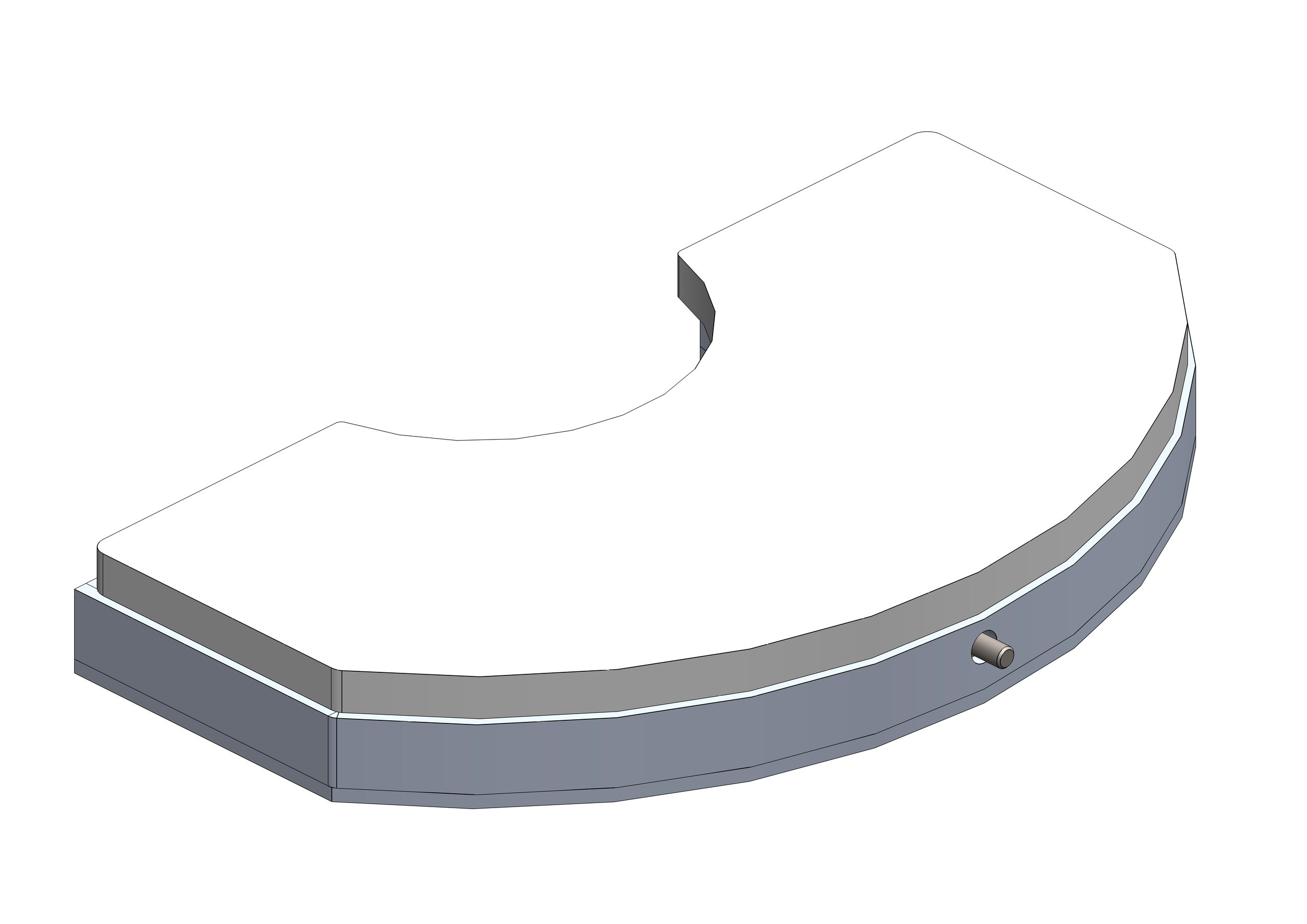
Items |
CE001136 |
CE001132 |
CE001134 |
|---|---|---|---|
LED color |
red |
infrared |
white |
Wavelength |
630 nm |
850 nm |
N/A |
Voltage |
24VDC |
24VDC |
24VDC |
Current |
0.17A |
0.12A |
0.17A |
Illumination area |
155x75 mm^2 |
||
Frame material |
Aluminum alloy |
||
Operating temperature |
-40 / +85 °C |
||
Cable length |
0.2 m |
||
Cooling method |
Natural air |
||
Opal material |
3+3 glass with milk-white plastic |
Backlight for FB350
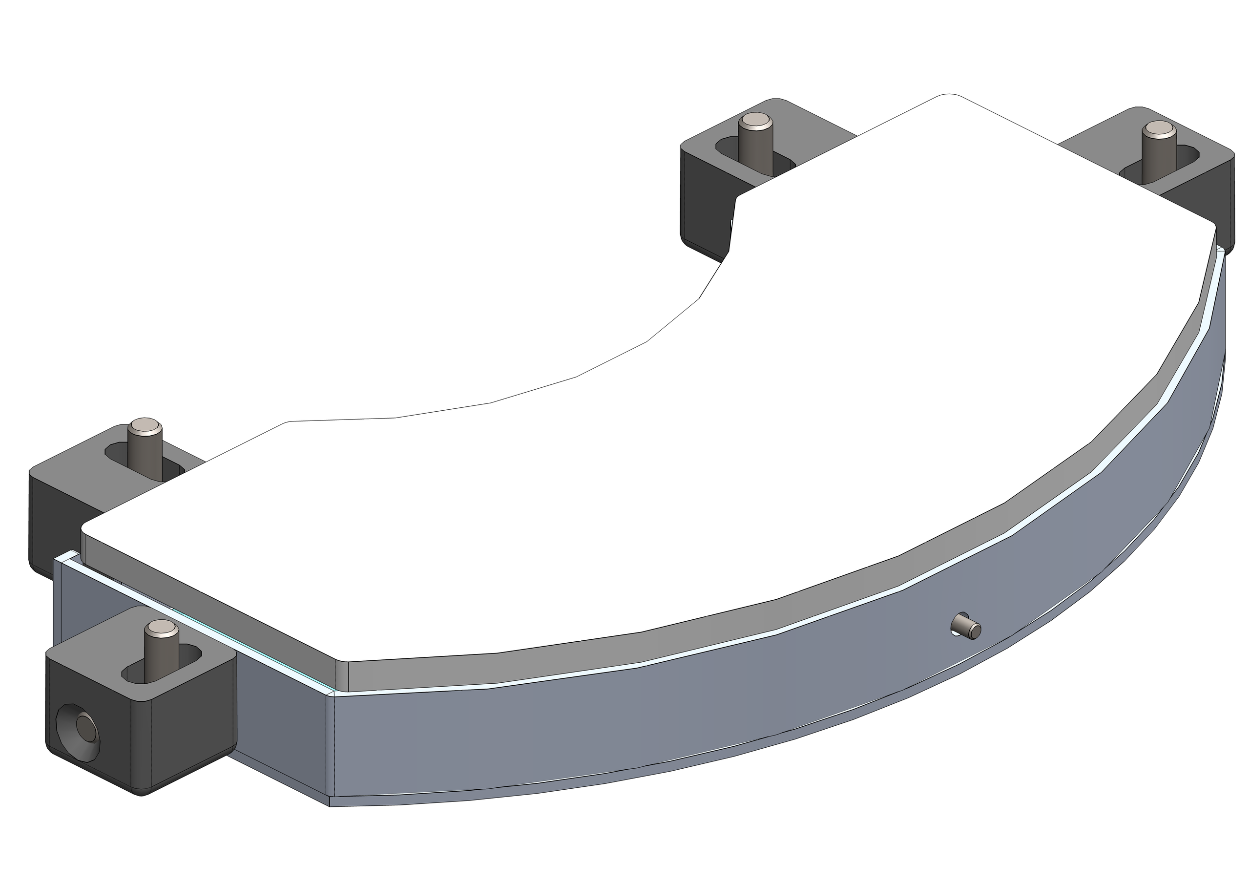
Items |
CE001142 |
CE001139 |
CE001140 |
|---|---|---|---|
LED color |
red |
infrared |
white |
Wavelength |
630 nm |
850 nm |
N/A |
Voltage |
24VDC |
24VDC |
24VDC |
Current |
0.18A |
0.13A |
0.18A |
Illumination area |
220x100 mm^2 |
||
Frame material |
Aluminum alloy |
||
Operating temperature |
-40 / +85 °C |
||
Cable length |
0.2 m |
||
Cooling method |
Natural air |
||
Opal material |
3+3 glass with milk-white plastic |
Backlight for FB500
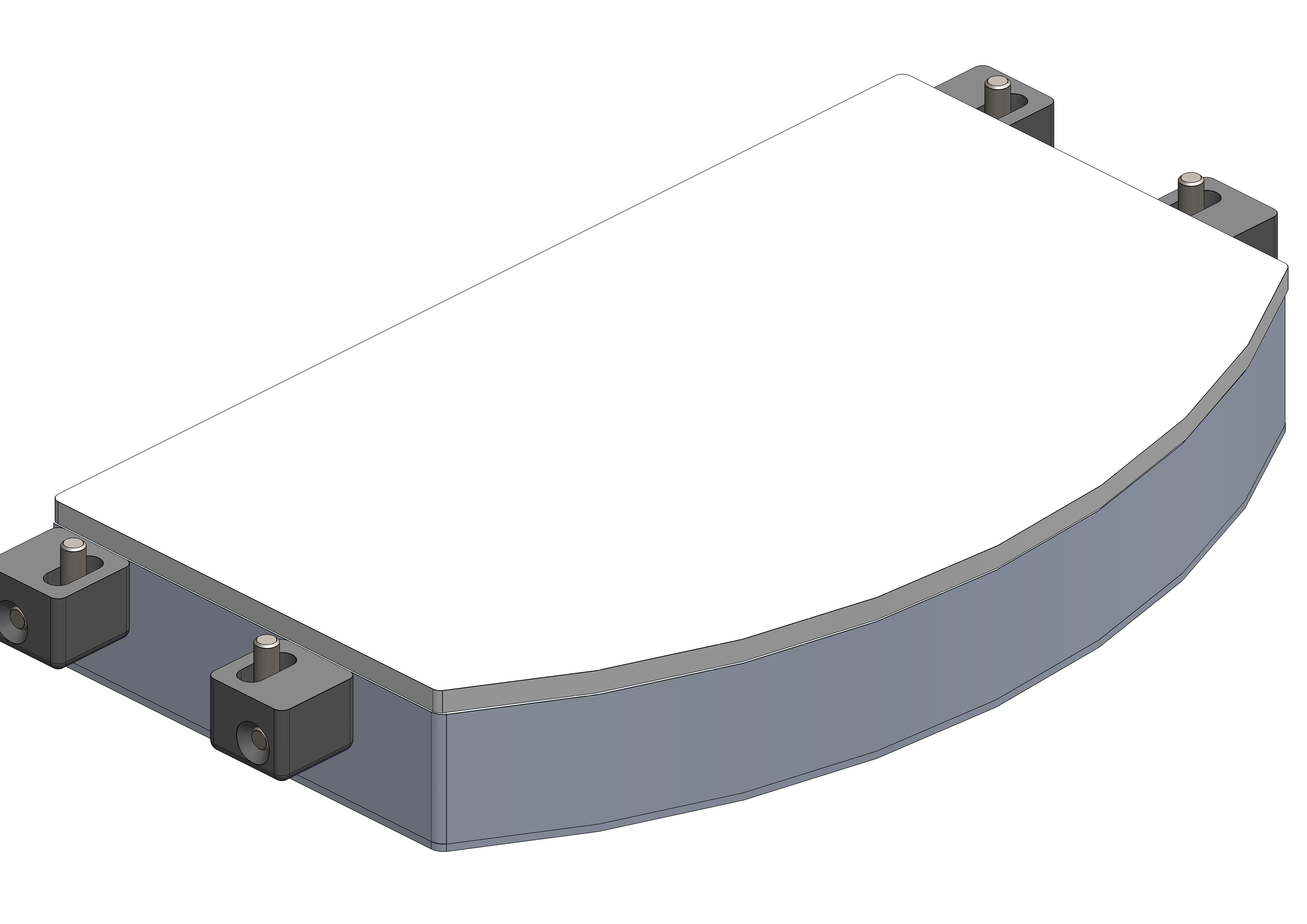
Items |
CE001148 |
CE001144 |
CE001146 |
|---|---|---|---|
LED color |
red |
infrared |
white |
Wavelength |
630 nm |
850 nm |
N/A |
Voltage |
24VDC |
24VDC |
24VDC |
Current |
0.46A |
0.31A |
0.46A |
Illumination area |
330x170 mm^2 |
||
Frame material |
Aluminum alloy |
||
Operating temperature |
-40 / +85 °C |
||
Cable length |
0.2 m |
||
Cooling method |
Natural air |
||
Opal material |
3+3 glass with milk-white plastic |
Backlight for FB650
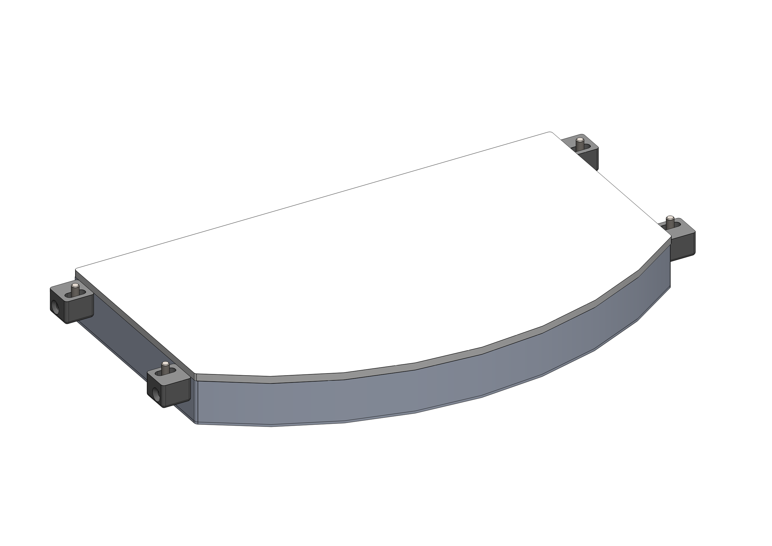
Items |
CE000306 |
CE000273 |
CE000305 |
|---|---|---|---|
Alternative items |
GM000591 |
GM000592 |
GM000590 |
LED color |
red |
infrared |
white |
Wavelength |
630 nm |
850 nm |
N/A |
Voltage |
24VDC |
24VDC |
24VDC |
Current |
0.86A |
0.56A |
0.94A |
Illumination area |
400x240 mm^2 |
||
Frame material |
Aluminum alloy |
||
Operating temperature |
-40 / +85 °C |
||
Cable length |
0.2 m |
||
Cooling method |
Natural air |
||
Opal material |
3+3 glass with milk-white plastic |
Backlight for FB800
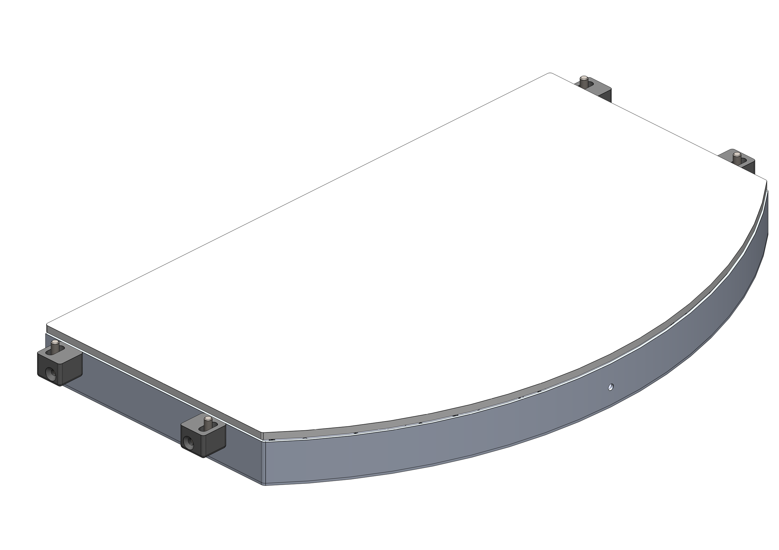
Items |
CE001154 |
CE001150 |
CE001152 |
|---|---|---|---|
LED color |
red |
infrared |
white |
Wavelength |
630 nm |
850 nm |
N/A |
Voltage |
24VDC |
24VDC |
24VDC |
Current |
1.15A |
0.76A |
1.2A |
Illumination area |
400x315 mm^2 |
||
Frame material |
Aluminum alloy |
||
Operating temperature |
-40 / +85 °C |
||
Cable length |
0.2 m |
||
Cooling method |
Natural air |
||
Opal material |
3+3 glass with milk-white plastic |
Backlight for FB1200
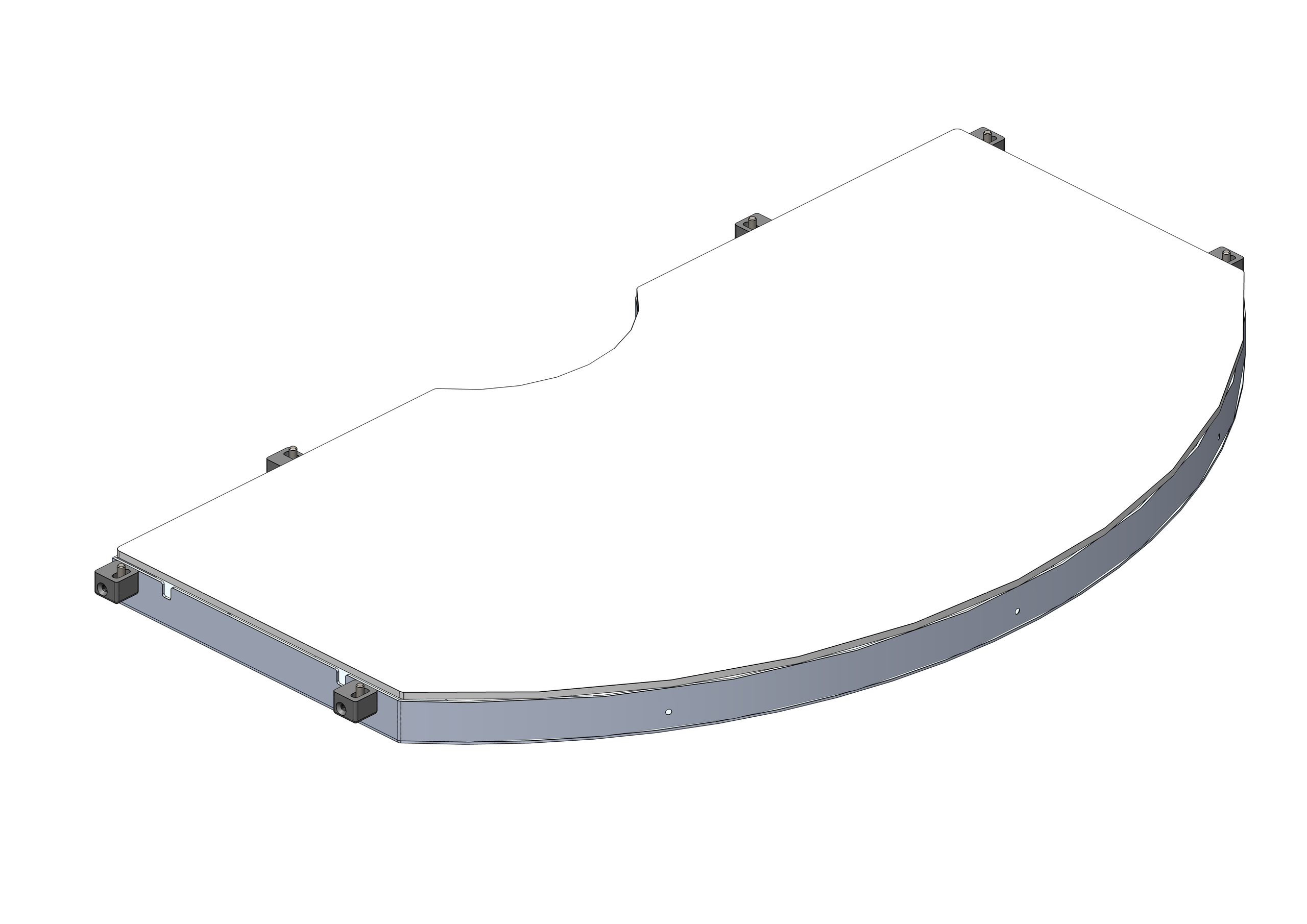
Items |
GE000051 |
GE000052 |
GE000050 |
|---|---|---|---|
LED color |
red |
infrared |
white |
Wavelength |
630 nm |
850 nm |
N/A |
Voltage |
24VDC |
24VDC |
24VDC |
Current |
4A |
2.6A |
4.2A |
Illumination area |
917x525 mm^2 |
||
Frame material |
Aluminum alloy |
||
Operating temperature |
-40 / +85 °C |
||
Cable length |
0.2 m |
||
Cooling method |
Natural air |
||
Opal material |
3+3 glass with milk-white plastic |
Backlight colors#
Color |
Wavelength |
Recommended use |
|---|---|---|
Red |
630 nm |
Used for special metal components. Wavelength: 630 nm. The cell must be shielded from any external light source and from sunlight. |
IR |
850 nm |
Preferred for most types of applications. Not visible to the human eye. Wavelength: 850 nm. Shielding the cell is recommended to avoid interference from sunlight. |
White |
N/A |
Used with transparent components. The cell must be shielded from any external light source and from sunlight. |
Toplight#
The Toplight is a separate illuminator that is mounted at the height of the camera and illuminates the vision area of the FlexiBowl® from above, so that the features of the component facing the camera are highlighted. It is mainly suitable for smooth, non-reflective surfaces, or surfaces with some kind of distinguishable marking. The Toplight is available with the following light colors:
White
Red
Infrared
Important
The infrared Toplight emits invisible light and may therefore appear not to be working. Check it with a camera fitted with an infrared filter to verify that it works. Most smartphones can display infrared.
Toplight characteristics#
White Toplight 200/350/500
This Toplight size is suitable for the following models: FlexiBowl® 200, FlexiBowl® 350, FlexiBowl® 500
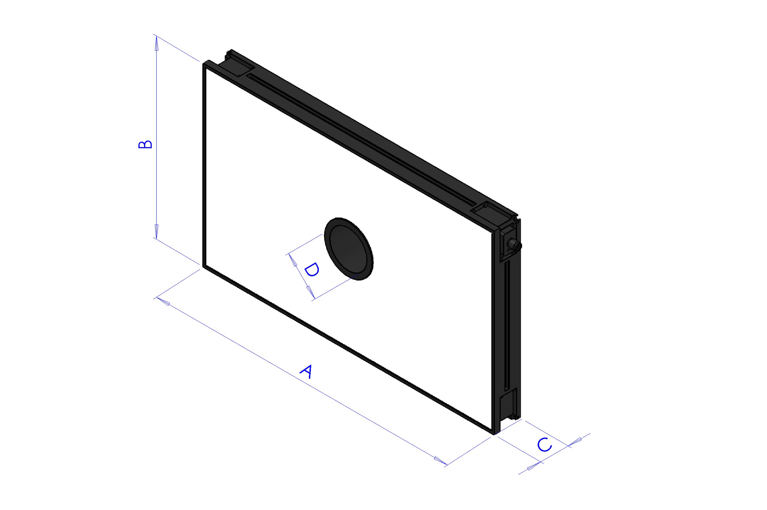
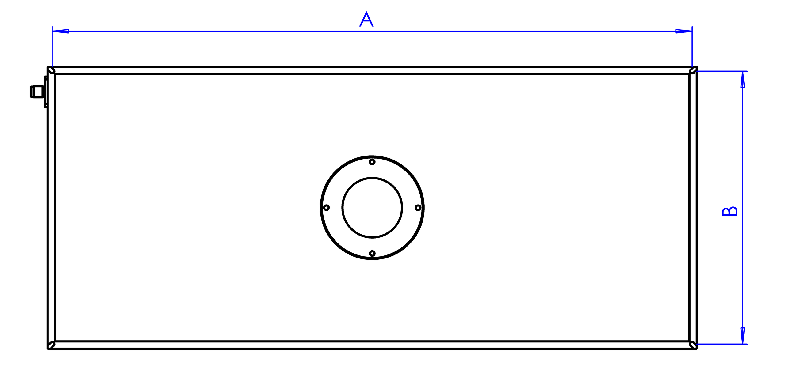
Length |
Width |
Height |
Height with mounting plate |
Center hole diameter |
Max usable area [AxB] |
Max usable perimeter |
|---|---|---|---|---|---|---|
A |
B |
C |
C + 10mm |
D |
- |
- |
500 |
300 |
45 |
55 |
65 |
0.15 m^2 |
1.6 m |
Code |
CM002316 |
Electronics |
|
Power supply |
24 VDC ±10% |
Control mode |
Continuous |
Maximum rise time |
15 µs |
Maximum fall time |
10 µs |
Control |
|
Connector pin configuration |
1: 24VDC / 3: GND / 4: PNP |
Consumption |
96.6W |
Minimum operating voltage |
20V on the light input |
Nominal operating voltage |
24V on the light input (±10%) |
Maximum operating voltage |
30V on the light input |
Wavelength |
|
Risk Group |
0 (no risk) |
Mechanical |
|
Thickness |
45mm + 10mm with mounting plate |
Inner diameter |
65mm |
Weight |
23.8 Kg/m² ±15% |
Materials |
Aluminum and filled ABS |
Diffuser |
White PMMA |
Mounting |
4 M4 nuts (supplied) to be inserted in the groove, or 4 M4x20 screws (not supplied) applied at the corners |
Environment |
|
Operating temperature |
-10°C to +40°C / 80% humidity, non-condensing. No thermal shock (maximum variation: 10°C in 24h) |
Storage temperature |
-20°C to +60°C / 80% humidity, non-condensing. No thermal shock (maximum variation: 10°C in 24h) |
IP protection rating |
IP 50 |
Markings |
RoHS-CE-DEEE, UL |
Red Toplight 200/350/500
This Toplight size is suitable for the following models: FlexiBowl® 200, FlexiBowl® 350, FlexiBowl® 500
Length |
Width |
Height |
Height with mounting plate |
Center hole diameter |
Max usable area [AxB] |
Max usable perimeter |
|---|---|---|---|---|---|---|
A |
B |
C |
C + 10mm |
D |
- |
- |
500 |
300 |
45 |
55 |
65 |
0.15 m^2 |
1.6 m |
Code |
CM002401 |
Electronics |
|
Power supply |
24 VDC ±10% |
Control mode |
Continuous |
Maximum rise time |
15 µs |
Maximum fall time |
10 µs |
Control |
|
Connector pin configuration |
1: 24VDC / 3: GND / 4: PNP |
Consumption |
96.6W @24 Vdc |
Minimum operating voltage |
20V on the light input |
Nominal operating voltage |
24V on the light input (±10%) |
Maximum operating voltage |
30V on the light input |
Wavelength |
630 nm |
Risk Group |
0 (no risk) |
Mechanical |
|
Thickness |
45mm + 10mm with mounting plate |
Inner diameter |
65mm |
Weight |
23.8 Kg/m² ±15% |
Materials |
Aluminum and filled ABS |
Diffuser |
White PMMA |
Mounting |
4 M4 nuts (supplied) to be inserted in the groove, or 4 M4x20 screws (not supplied) applied at the corners |
Environment |
|
Operating temperature |
-10°C to +40°C / 80% humidity, non-condensing. No thermal shock (maximum variation: 10°C in 24h) |
Storage temperature |
-20°C to +60°C / 80% humidity, non-condensing. No thermal shock (maximum variation: 10°C in 24h) |
IP protection rating |
IP 50 |
Markings |
RoHS-CE-DEEE, UL |
IR Toplight 200/350/500
This Toplight size is suitable for the following models: FlexiBowl® 200, FlexiBowl® 350, FlexiBowl® 500
Length |
Width |
Height |
Height with mounting plate |
Center hole diameter |
Max usable area [AxB] |
Max usable perimeter |
|---|---|---|---|---|---|---|
A |
B |
C |
C + 10mm |
D |
- |
- |
500 |
300 |
45 |
55 |
65 |
0.15 m^2 |
1.6 m |
Code |
CM002405 |
Electronics |
|
Power supply |
24 VDC ±10% |
Control mode |
Continuous |
Maximum rise time |
15 µs |
Maximum fall time |
10 µs |
Control |
|
Connector pin configuration |
1: 24VDC / 3: GND / 4: PNP |
Consumption |
96.6W @24 Vdc |
Minimum operating voltage |
20V on the light input |
Nominal operating voltage |
24V on the light input (±10%) |
Maximum operating voltage |
30V on the light input |
Wavelength |
850 nm |
Risk Group |
1 (low risk) |
Mechanical |
|
Thickness |
45mm + 10mm with mounting plate |
Inner diameter |
65mm |
Weight |
23.8 Kg/m² ±15% |
Materials |
Aluminum and filled ABS |
Diffuser |
White PMMA |
Mounting |
4 M4 nuts (supplied) to be inserted in the groove, or 4 M4x20 screws (not supplied) applied at the corners |
Environment |
|
Operating temperature |
-10°C to +40°C / 80% humidity, non-condensing. No thermal shock (maximum variation: 10°C in 24h) |
Storage temperature |
-20°C to +60°C / 80% humidity, non-condensing. No thermal shock (maximum variation: 10°C in 24h) |
IP protection rating |
IP 50 |
Markings |
RoHS-CE-DEEE, UL |
White Toplight 650/800
This Toplight size is suitable for the following models: FlexiBowl® 650, FlexiBowl® 800
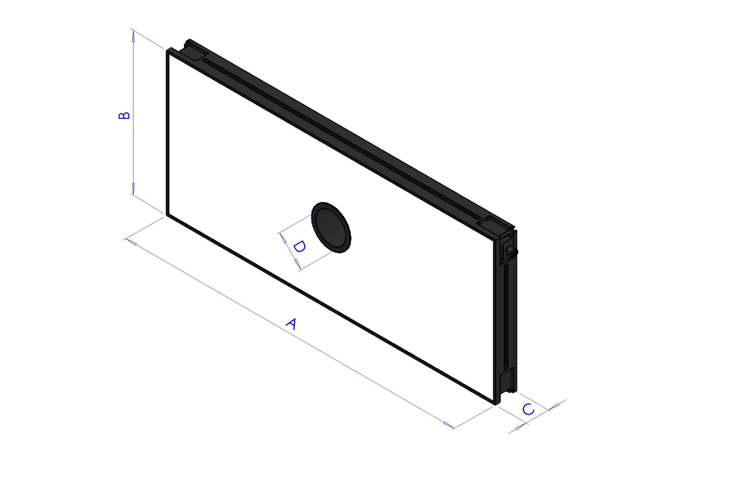
Length |
Width |
Height |
Height with mounting plate |
Center hole diameter |
Max usable area [AxB] |
Max usable perimeter |
|---|---|---|---|---|---|---|
A |
B |
C |
C + 10mm |
D |
- |
- |
700 |
300 |
45 |
55 |
65 |
0.21 m^2 |
2 m |
Code |
CM002317 |
Electronics |
|
Power supply |
24 VDC ±10% |
Control mode |
Continuous |
Maximum rise time |
15 µs |
Maximum fall time |
10 µs |
Control |
|
Connector pin configuration |
1: 24VDC / 3: GND / 4: PNP |
Consumption |
135.6W @24 Vdc |
Minimum operating voltage |
20V on the light input |
Nominal operating voltage |
24V on the light input (±10%) |
Maximum operating voltage |
30V on the light input |
Wavelength |
|
Risk Group |
0 (no risk) |
Mechanical |
|
Thickness |
45mm + 10mm with mounting plate |
Inner diameter |
65mm |
Weight |
23.8 Kg/m² ±15% |
Materials |
Aluminum and filled ABS |
Diffuser |
White PMMA |
Mounting |
4 M4 nuts (supplied) to be inserted in the groove, or 4 M4x20 screws (not supplied) applied at the corners |
Environment |
|
Operating temperature |
-10°C to +40°C / 80% humidity, non-condensing. No thermal shock (maximum variation: 10°C in 24h) |
Storage temperature |
-20°C to +60°C / 80% humidity, non-condensing. No thermal shock (maximum variation: 10°C in 24h) |
IP protection rating |
IP 50 |
Markings |
RoHS-CE-DEEE, UL |
Red Toplight 650/800
This Toplight size is suitable for the following models: FlexiBowl® 650, FlexiBowl® 800
Length |
Width |
Height |
Height with mounting plate |
Center hole diameter |
Max usable area [AxB] |
Max usable perimeter |
|---|---|---|---|---|---|---|
A |
B |
C |
C + 10mm |
D |
- |
- |
700 |
300 |
45 |
55 |
65 |
0.21 m^2 |
2 m |
Code |
CM002402 |
Electronics |
|
Power supply |
24 VDC ±10% |
Control mode |
Continuous |
Maximum rise time |
15 µs |
Maximum fall time |
10 µs |
Control |
|
Connector pin configuration |
1: 24VDC / 3: GND / 4: PNP |
Consumption |
135.6W @24 Vdc |
Minimum operating voltage |
20V on the light input |
Nominal operating voltage |
24V on the light input (±10%) |
Maximum operating voltage |
30V on the light input |
Wavelength |
630 nm |
Risk Group |
0 (no risk) |
Mechanical |
|
Thickness |
45mm + 10mm with mounting plate |
Inner diameter |
65mm |
Weight |
23.8 Kg/m² ±15% |
Materials |
Aluminum and filled ABS |
Diffuser |
White PMMA |
Mounting |
4 M4 nuts (supplied) to be inserted in the groove, or 4 M4x20 screws (not supplied) applied at the corners |
Environment |
|
Operating temperature |
-10°C to +40°C / 80% humidity, non-condensing. No thermal shock (maximum variation: 10°C in 24h) |
Storage temperature |
-20°C to +60°C / 80% humidity, non-condensing. No thermal shock (maximum variation: 10°C in 24h) |
IP protection rating |
IP 50 |
Markings |
RoHS-CE-DEEE, UL |
IR Toplight 650/800
This Toplight size is suitable for the following models: FlexiBowl® 650, FlexiBowl® 800
Length |
Width |
Height |
Height with mounting plate |
Center hole diameter |
Max usable area [AxB] |
Max usable perimeter |
|---|---|---|---|---|---|---|
A |
B |
C |
C + 10mm |
D |
- |
- |
700 |
300 |
45 |
55 |
65 |
0.21 m^2 |
2 m |
Code |
CM002406 |
Electronics |
|
Power supply |
24 VDC ±10% |
Control mode |
Continuous |
Maximum rise time |
15 µs |
Maximum fall time |
10 µs |
Control |
|
Connector pin configuration |
1: 24VDC / 3: GND / 4: PNP |
Consumption |
135.6W @24 Vdc |
Minimum operating voltage |
20V on the light input |
Nominal operating voltage |
24V on the light input (±10%) |
Maximum operating voltage |
30V on the light input |
Wavelength |
850 nm |
Risk Group |
1 (low risk) |
Mechanical |
|
Thickness |
45mm + 10mm with mounting plate |
Inner diameter |
65mm |
Weight |
23.8 Kg/m² ±15% |
Materials |
Aluminum and filled ABS |
Diffuser |
White PMMA |
Mounting |
4 M4 nuts (supplied) to be inserted in the groove, or 4 M4x20 screws (not supplied) applied at the corners |
Environment |
|
Operating temperature |
-10°C to +40°C / 80% humidity, non-condensing. No thermal shock (maximum variation: 10°C in 24h) |
Storage temperature |
-20°C to +60°C / 80% humidity, non-condensing. No thermal shock (maximum variation: 10°C in 24h) |
IP protection rating |
IP 50 |
Markings |
RoHS-CE-DEEE, UL |
White Toplight 650/800 XXL
This Toplight size is suitable for the following models: FlexiBowl® 650, FlexiBowl® 800
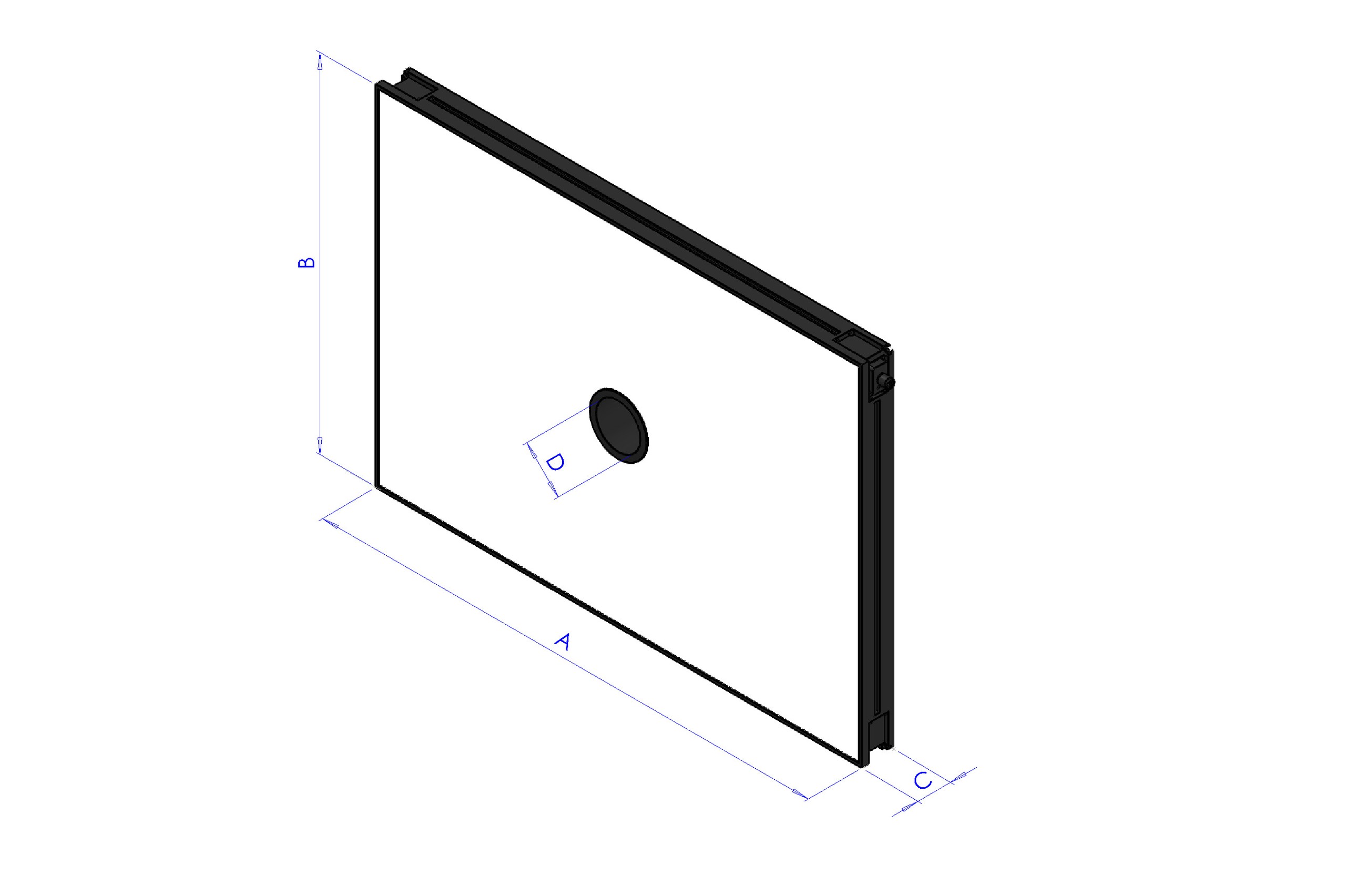
Length |
Width |
Height |
Height with mounting plate |
Center hole diameter |
Max usable area [AxB] |
Max usable perimeter |
|---|---|---|---|---|---|---|
A |
B |
C |
C + 10mm |
D |
- |
- |
700 |
500 |
45 |
55 |
65 |
0.35 m^2 |
2.4 m |
Code |
CM002318 |
Electronics |
|
Power supply |
24 VDC ±10% |
Control mode |
Continuous |
Maximum rise time |
15 µs |
Maximum fall time |
10 µs |
Control |
|
Connector pin configuration |
1: 24VDC / 3: GND / 4: PNP |
Consumption |
252.6W @24 Vdc |
Minimum operating voltage |
20V on the light input |
Nominal operating voltage |
24V on the light input (±10%) |
Maximum operating voltage |
30V on the light input |
Wavelength |
|
Risk Group |
0 (no risk) |
Mechanical |
|
Thickness |
45mm + 10mm with mounting plate |
Inner diameter |
65mm |
Weight |
23.8 Kg/m² ±15% |
Materials |
Aluminum and filled ABS |
Diffuser |
White PMMA |
Mounting |
4 M4 nuts (supplied) to be inserted in the groove, or 4 M4x20 screws (not supplied) applied at the corners |
Environment |
|
Operating temperature |
-10°C to +40°C / 80% humidity, non-condensing. No thermal shock (maximum variation: 10°C in 24h) |
Storage temperature |
-20°C to +60°C / 80% humidity, non-condensing. No thermal shock (maximum variation: 10°C in 24h) |
IP protection rating |
IP 50 |
Markings |
RoHS-CE-DEEE, UL |
Red Toplight 650/800 XXL
This Toplight size is suitable for the following models: FlexiBowl® 650, FlexiBowl® 800
Length |
Width |
Height |
Height with mounting plate |
Center hole diameter |
Max usable area [AxB] |
Max usable perimeter |
|---|---|---|---|---|---|---|
A |
B |
C |
C + 10mm |
D |
- |
- |
700 |
500 |
45 |
55 |
65 |
0.35 m^2 |
2.4 m |
Code |
CM002403 |
Electronics |
|
Power supply |
24 VDC ±10% |
Control mode |
Continuous |
Maximum rise time |
15 µs |
Maximum fall time |
10 µs |
Control |
|
Connector pin configuration |
1: 24VDC / 3: GND / 4: PNP |
Consumption |
252.6W @24 Vdc |
Minimum operating voltage |
20V on the light input |
Nominal operating voltage |
24V on the light input (±10%) |
Maximum operating voltage |
30V on the light input |
Wavelength |
630 nm |
Risk Group |
0 (no risk) |
Mechanical |
|
Thickness |
45mm + 10mm with mounting plate |
Inner diameter |
65mm |
Weight |
23.8 Kg/m² ±15% |
Materials |
Aluminum and filled ABS |
Diffuser |
White PMMA |
Mounting |
4 M4 nuts (supplied) to be inserted in the groove, or 4 M4x20 screws (not supplied) applied at the corners |
Environment |
|
Operating temperature |
-10°C to +40°C / 80% humidity, non-condensing. No thermal shock (maximum variation: 10°C in 24h) |
Storage temperature |
-20°C to +60°C / 80% humidity, non-condensing. No thermal shock (maximum variation: 10°C in 24h) |
IP protection rating |
IP 50 |
Markings |
RoHS-CE-DEEE, UL |
IR Toplight 650/800 XXL
This Toplight size is suitable for the following models: FlexiBowl® 650, FlexiBowl® 800
Length |
Width |
Height |
Height with mounting plate |
Center hole diameter |
Max usable area [AxB] |
Max usable perimeter |
|---|---|---|---|---|---|---|
A |
B |
C |
C + 10mm |
D |
- |
- |
700 |
500 |
45 |
55 |
65 |
0.35 m^2 |
2.4 m |
Code |
CM002407 |
Electronics |
|
Power supply |
24 VDC ±10% |
Control mode |
Continuous |
Maximum rise time |
15 µs |
Maximum fall time |
10 µs |
Control |
|
Connector pin configuration |
1: 24VDC / 3: GND / 4: PNP |
Consumption |
252.6W @24 Vdc |
Minimum operating voltage |
20V on the light input |
Nominal operating voltage |
24V on the light input (±10%) |
Maximum operating voltage |
30V on the light input |
Wavelength |
850 nm |
Risk Group |
1 (low risk) |
Mechanical |
|
Thickness |
45mm + 10mm with mounting plate |
Inner diameter |
65mm |
Weight |
23.8 Kg/m² ±15% |
Materials |
Aluminum and filled ABS |
Diffuser |
White PMMA |
Mounting |
4 M4 nuts (supplied) to be inserted in the groove, or 4 M4x20 screws (not supplied) applied at the corners |
Environment |
|
Operating temperature |
-10°C to +40°C / 80% humidity, non-condensing. No thermal shock (maximum variation: 10°C in 24h) |
Storage temperature |
-20°C to +60°C / 80% humidity, non-condensing. No thermal shock (maximum variation: 10°C in 24h) |
IP protection rating |
IP 50 |
Markings |
RoHS-CE-DEEE, UL |
White Toplight 1200
This Toplight size is suitable for the FlexiBowl® 1200 models
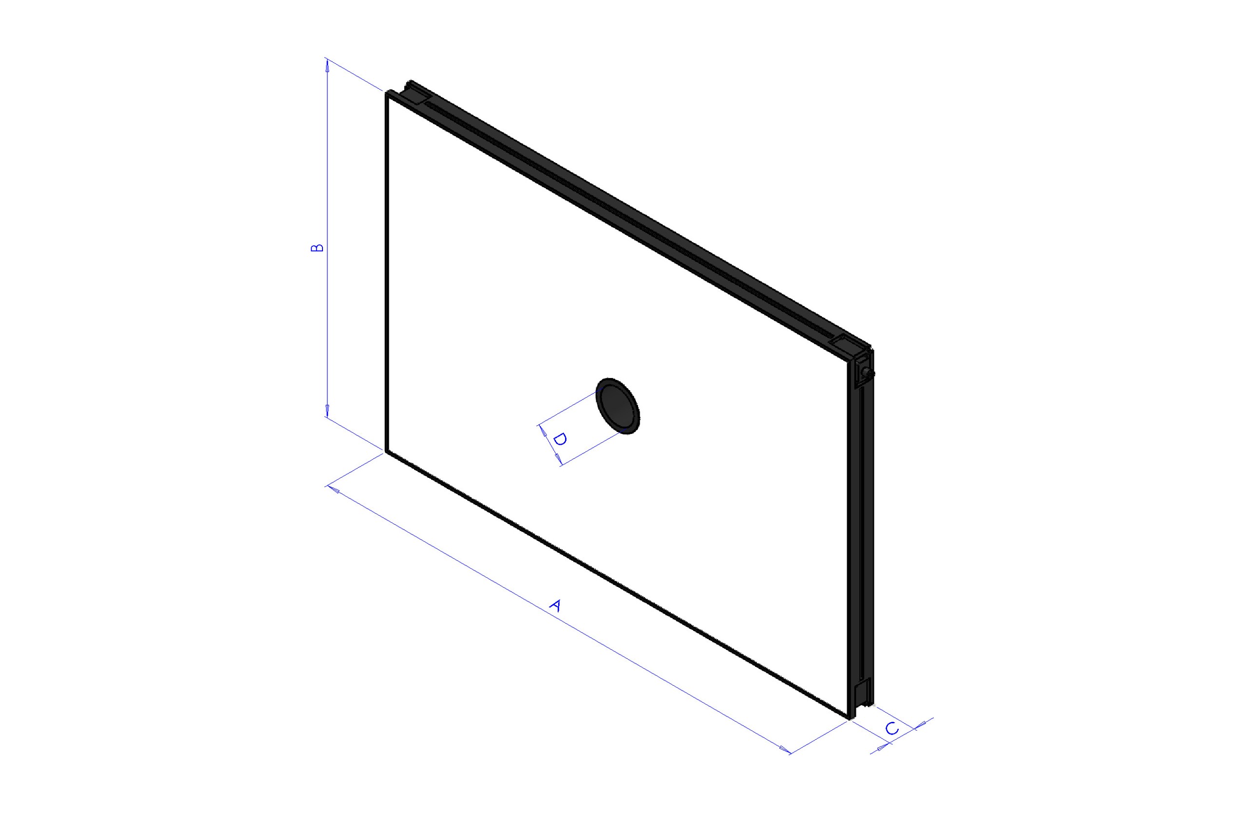
Length |
Width |
Height |
Height with mounting plate |
Center hole diameter |
Max usable area [AxB] |
Max usable perimeter |
|---|---|---|---|---|---|---|
A |
B |
C |
C + 10mm |
D |
- |
- |
900 |
600 |
45 |
55 |
65 |
0.54 m^2 |
3 m |
Code |
CM002319 |
Electronics |
|
Power supply |
24 VDC ±10% |
Control mode |
Continuous |
Maximum rise time |
15 µs |
Maximum fall time |
10 µs |
Control |
|
Connector pin configuration |
1: 24VDC / 3: GND / 4: PNP |
Consumption |
345.6W @24 Vdc |
Minimum operating voltage |
20V on the light input |
Nominal operating voltage |
24V on the light input (±10%) |
Maximum operating voltage |
30V on the light input |
Wavelength |
|
Risk Group |
0 (no risk) |
Mechanical |
|
Thickness |
45mm + 10mm with mounting plate |
Inner diameter |
65mm |
Weight |
23.8 Kg/m² ±15% |
Materials |
Aluminum and filled ABS |
Diffuser |
White PMMA |
Mounting |
4 M4 nuts (supplied) to be inserted in the groove, or 4 M4x20 screws (not supplied) applied at the corners |
Environment |
|
Operating temperature |
-10°C to +40°C / 80% humidity, non-condensing. No thermal shock (maximum variation: 10°C in 24h) |
Storage temperature |
-20°C to +60°C / 80% humidity, non-condensing. No thermal shock (maximum variation: 10°C in 24h) |
IP protection rating |
IP 50 |
Markings |
RoHS-CE-DEEE, UL |
Red Toplight 1200
This Toplight size is suitable for the FlexiBowl® 1200 models
Length |
Width |
Height |
Height with mounting plate |
Center hole diameter |
Max usable area [AxB] |
Max usable perimeter |
|---|---|---|---|---|---|---|
A |
B |
C |
C + 10mm |
D |
- |
- |
900 |
600 |
45 |
55 |
65 |
0.54 m^2 |
3 m |
Code |
CM002404 |
Electronics |
|
Power supply |
24 VDC ±10% |
Control mode |
Continuous |
Maximum rise time |
15 µs |
Maximum fall time |
10 µs |
Control |
|
Connector pin configuration |
1: 24VDC / 3: GND / 4: PNP |
Consumption |
345.6W @24 Vdc |
Minimum operating voltage |
20V on the light input |
Nominal operating voltage |
24V on the light input (±10%) |
Maximum operating voltage |
30V on the light input |
Wavelength |
630 nm |
Risk Group |
0 (no risk) |
Mechanical |
|
Thickness |
45mm + 10mm with mounting plate |
Inner diameter |
65mm |
Weight |
23.8 Kg/m² ±15% |
Materials |
Aluminum and filled ABS |
Diffuser |
White PMMA |
Mounting |
4 M4 nuts (supplied) to be inserted in the groove, or 4 M4x20 screws (not supplied) applied at the corners |
Environment |
|
Operating temperature |
-10°C to +40°C / 80% humidity, non-condensing. No thermal shock (maximum variation: 10°C in 24h) |
Storage temperature |
-20°C to +60°C / 80% humidity, non-condensing. No thermal shock (maximum variation: 10°C in 24h) |
IP protection rating |
IP 50 |
Markings |
RoHS-CE-DEEE, UL |
IR Toplight 1200
This Toplight size is suitable for the FlexiBowl® 1200 models
Length |
Width |
Height |
Height with mounting plate |
Center hole diameter |
Max usable area [AxB] |
Max usable perimeter |
|---|---|---|---|---|---|---|
A |
B |
C |
C + 10mm |
D |
- |
- |
900 |
600 |
45 |
55 |
65 |
0.54 m^2 |
3 m |
Code |
CM002408 |
Electronics |
|
Power supply |
24 VDC ±10% |
Control mode |
Continuous |
Maximum rise time |
15 µs |
Maximum fall time |
10 µs |
Control |
|
Connector pin configuration |
1: 24VDC / 3: GND / 4: PNP |
Consumption |
345.6W @24 Vdc |
Minimum operating voltage |
20V on the light input |
Nominal operating voltage |
24V on the light input (±10%) |
Maximum operating voltage |
30V on the light input |
Wavelength |
850 nm |
Risk Group |
1 (low risk) |
Mechanical |
|
Thickness |
45mm + 10mm with mounting plate |
Inner diameter |
65mm |
Weight |
23.8 Kg/m² ±15% |
Materials |
Aluminum and filled ABS |
Diffuser |
White PMMA |
Mounting |
4 M4 nuts (supplied) to be inserted in the groove, or 4 M4x20 screws (not supplied) applied at the corners |
Environment |
|
Operating temperature |
-10°C to +40°C / 80% humidity, non-condensing. No thermal shock (maximum variation: 10°C in 24h) |
Storage temperature |
-20°C to +60°C / 80% humidity, non-condensing. No thermal shock (maximum variation: 10°C in 24h) |
IP protection rating |
IP 50 |
Markings |
RoHS-CE-DEEE, UL |
Toplight colors#
Color |
Wavelength |
Recommended use |
|---|---|---|
Red |
630 nm |
Used for special metal components. Wavelength: 630 nm. The cell must be shielded from any external light source and from sunlight. |
IR |
850 nm |
Preferred for most types of applications. Not visible to the human eye. Wavelength: 850 nm. Shielding the cell is recommended to avoid interference from sunlight. |
White |
N/A |
Used with transparent components. The cell must be shielded from any external light source and from sunlight. |
Toplight Power Cable#
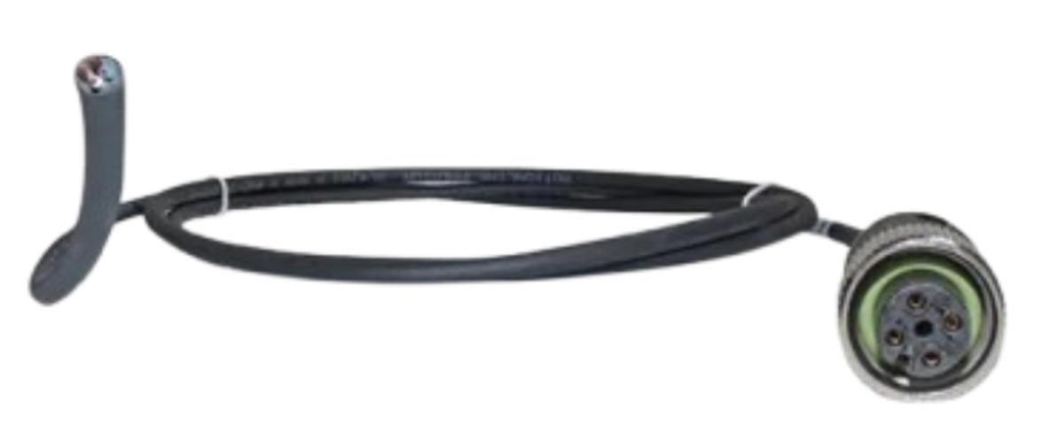
Code |
Description |
Connector |
|---|---|---|
CE001337 |
Toplight Power Cable 2M |
M12 4 Pin Female |
CE001338 |
Toplight Power Cable 5M |
M12 4 Pin Female |
CE001339 |
Toplight Power Cable 10M |
M12 4 Pin Female |
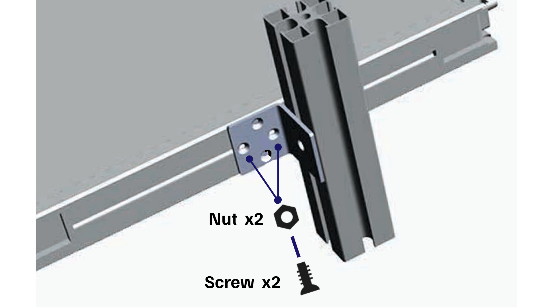
Toplight Mounting Bracket#
For mounting the toplight on the side, a dedicated bracket can be purchased separately.
Toplight mounting#
If the order includes a Toplight (overhead illuminator), it must be mounted on the same support structure as the camera to ensure uniform illumination of the work surface.
Attention
During installation, the device must be switched off and disconnected from the power supply.
Toplight dimensions#
Length x Width (mm) |
Height (mm) |
Height with mounting plate (mm) |
Center hole diameter |
Maximum usable area [A x B] |
Maximum usable perimeter |
|---|---|---|---|---|---|
A x B |
C |
C + 10 mm |
D |
– |
– |
500x300 |
45 |
55 |
65 |
0.15 m² |
1.6 m |
700x300 |
45 |
55 |
65 |
0.21 m² |
2 m |
700x500 |
45 |
55 |
65 |
0.35 m² |
2.4 m |
900x600 |
45 |
55 |
65 |
0.54 m² |
3 m |
Toplight positioning#
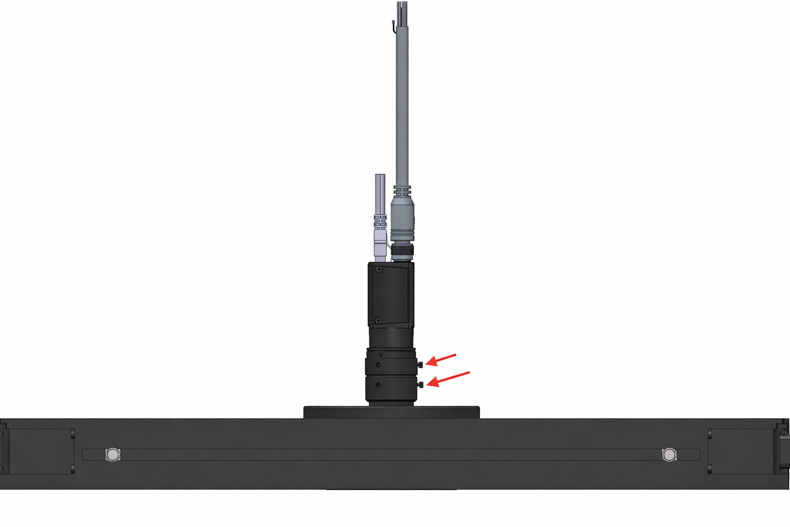
The toplight must be positioned centrally with respect to the usable surface of the light panel, with the camera optics mounted inside the central hole, flush with the top surface of the toplight. The red arrows indicate the fixing screws of the lens rings, one for focus adjustment and one for aperture adjustment. As shown in the figure, the toplight must be mounted so that the two screws remain accessible from above.
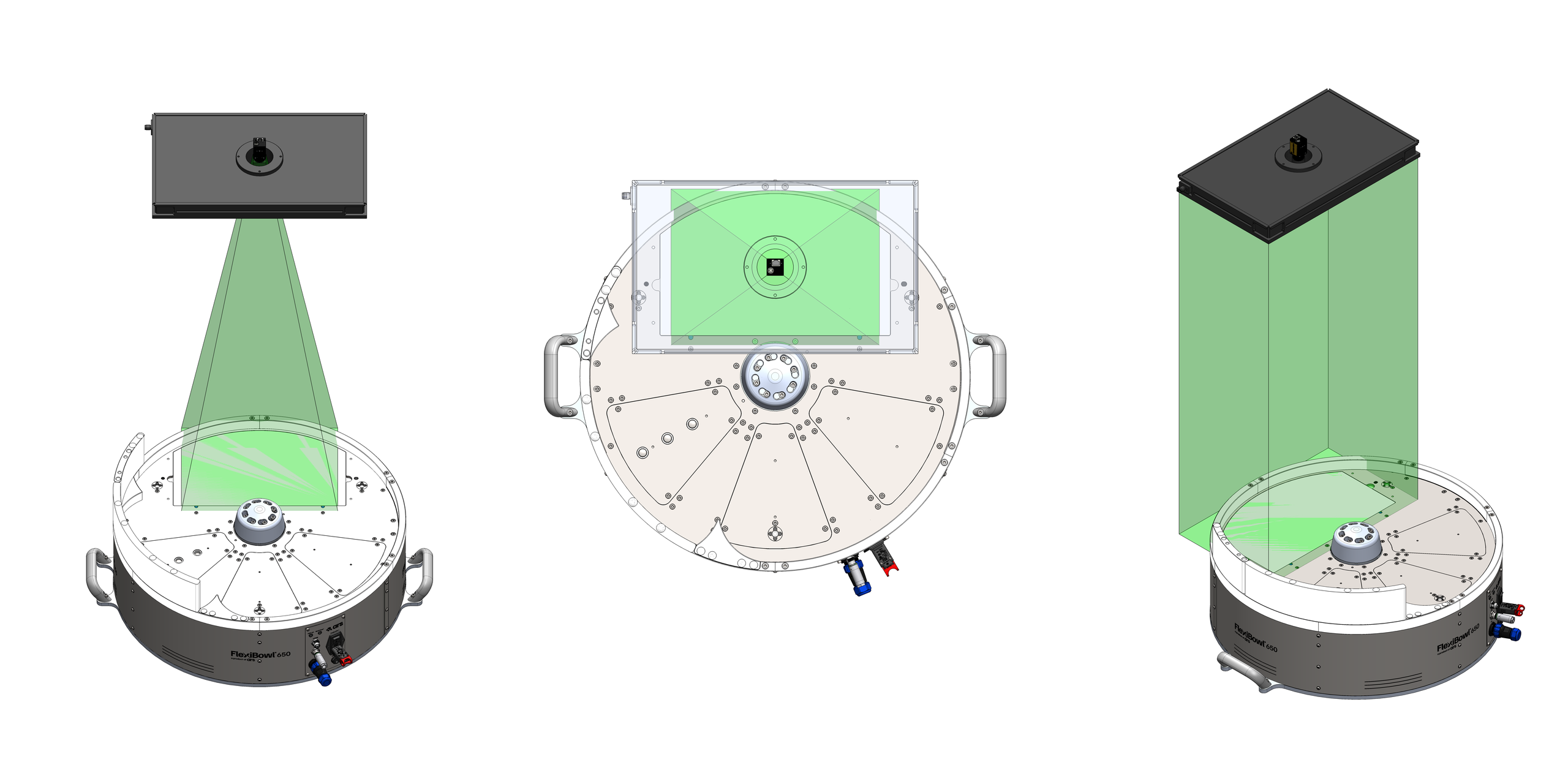
The camera’s field of view and the toplight’s light beam (in green) must be aligned concentrically and perpendicular to the viewing area on the FlexiBowl®. As shown in the three views (front, top and axonometric), the toplight must illuminate exactly the area framed by the camera, with both components centered on the vertical optical axis of the system.
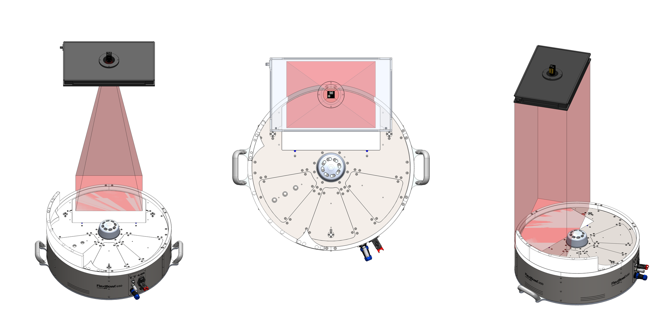
Incorrect positioning occurs when the toplight and the camera are not centered on the viewing area of the FlexiBowl®. As illustrated (in red), two typical errors are:
shifting forward or backward relative to the viewing area.
rotating the toplight relative to it.
In both cases, the illumination is off-axis and not perpendicular, compromising the quality of the image acquisition.
Installation procedure#
Step |
Operating instructions |
|---|---|
1. Positioning |
Fix the Toplight to the support structure in a position concentric with the camera. |
2. Distance from the surface |
Position the illuminator at a distance from the FlexiBowl® surface similar to that of the camera in order to:
|
3. Orientation |
Make sure that the emitting surface of the Toplight is parallel to the working surface of the FlexiBowl®. |
4. Illumination angle |
Perpendicular to the surface (0° tilt). |
5. Mounting |
According to the specifications of the chosen method (see next section). |
Mounting methods#
The Toplight can be mounted in two ways: at the corner or on the side.
Note
The fastening components are not included in the Toplight supply. The mounting can therefore be customized according to the needs of the installation.
Side mounting (groove): M4 nuts supplied
Corner mounting: M4x20 socket head cap screws not supplied
In both cases, the use of a threadlocker (not supplied) is recommended to prevent loosening over time. The recommended tightening torque is between 0.5 and 1.5 Nm.
1. Corner mounting#
Corner mounting uses M4x20 socket head cap screws (not supplied) fitted into the holes located at the four corners of the Toplight.
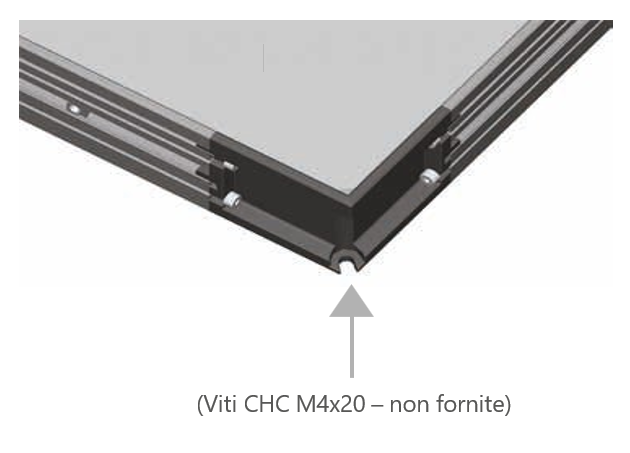
Corner mounting using an M4x20 socket head cap screw (not supplied).#
2. Side mounting (groove)#
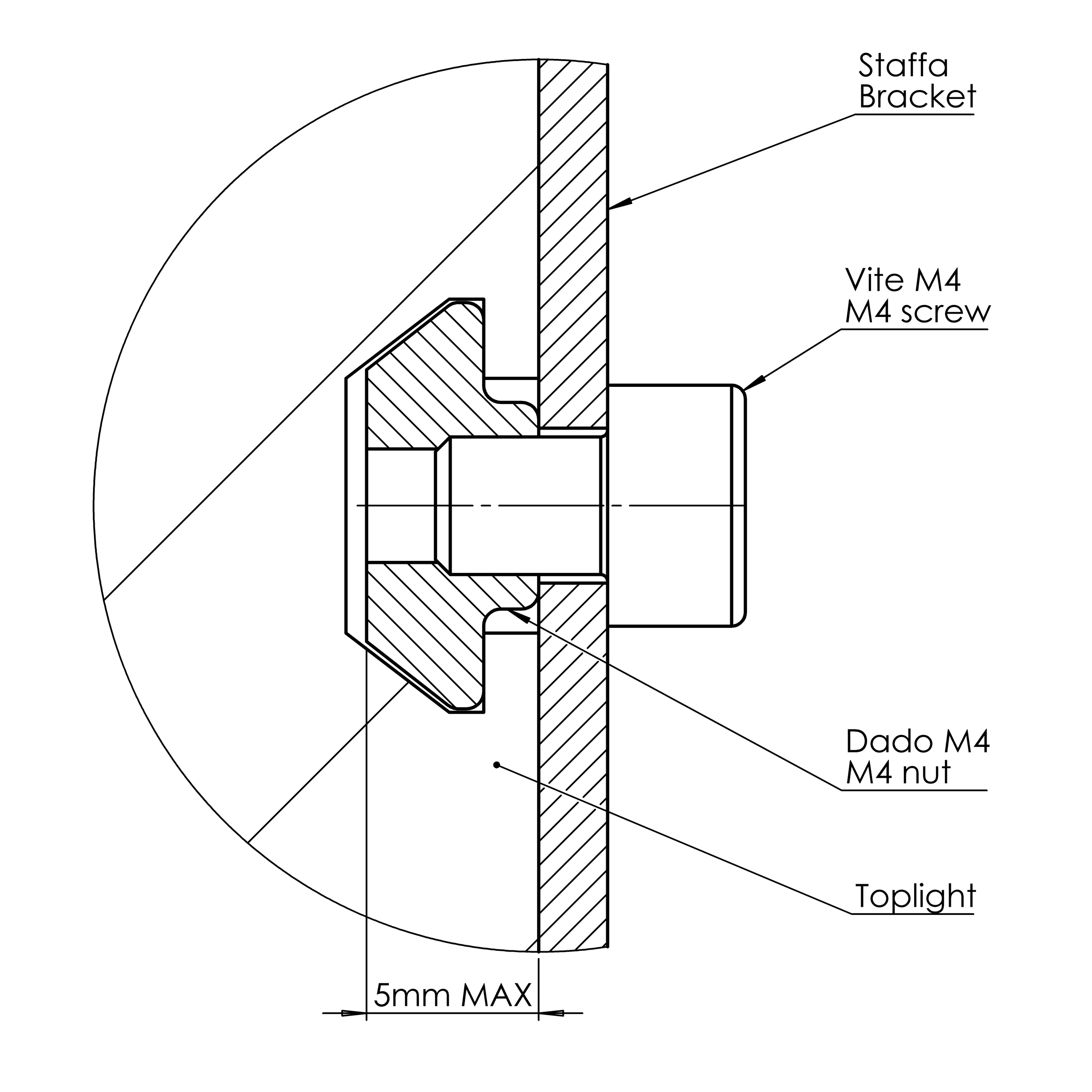
Side mounting uses 4 M4 nuts (supplied) to be inserted into the side groove of the Toplight profile. The maximum insertion depth of the nut in the groove is 5 mm. The recommended screws are M4x8.
Side mounting#
Side mounting with brackets#
If the Toplight is fixed with brackets:
Error
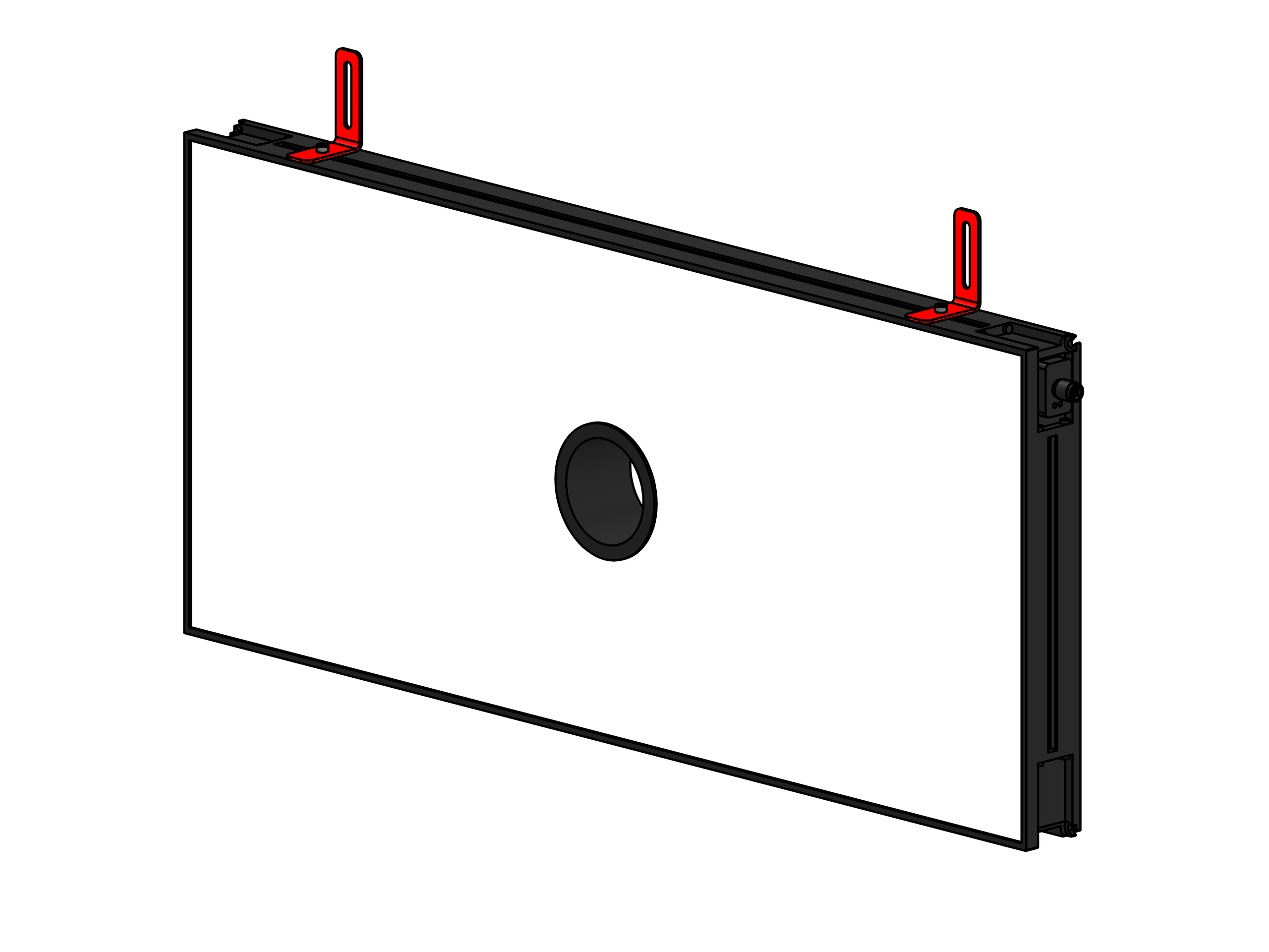
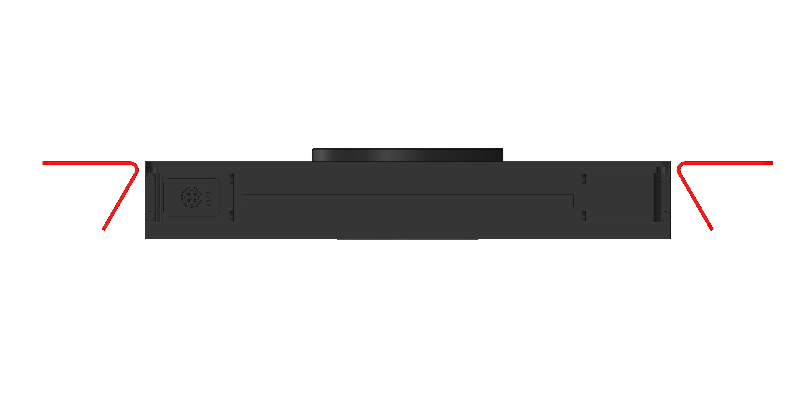
Tip
Some examples of correct Toplight mounting follow:
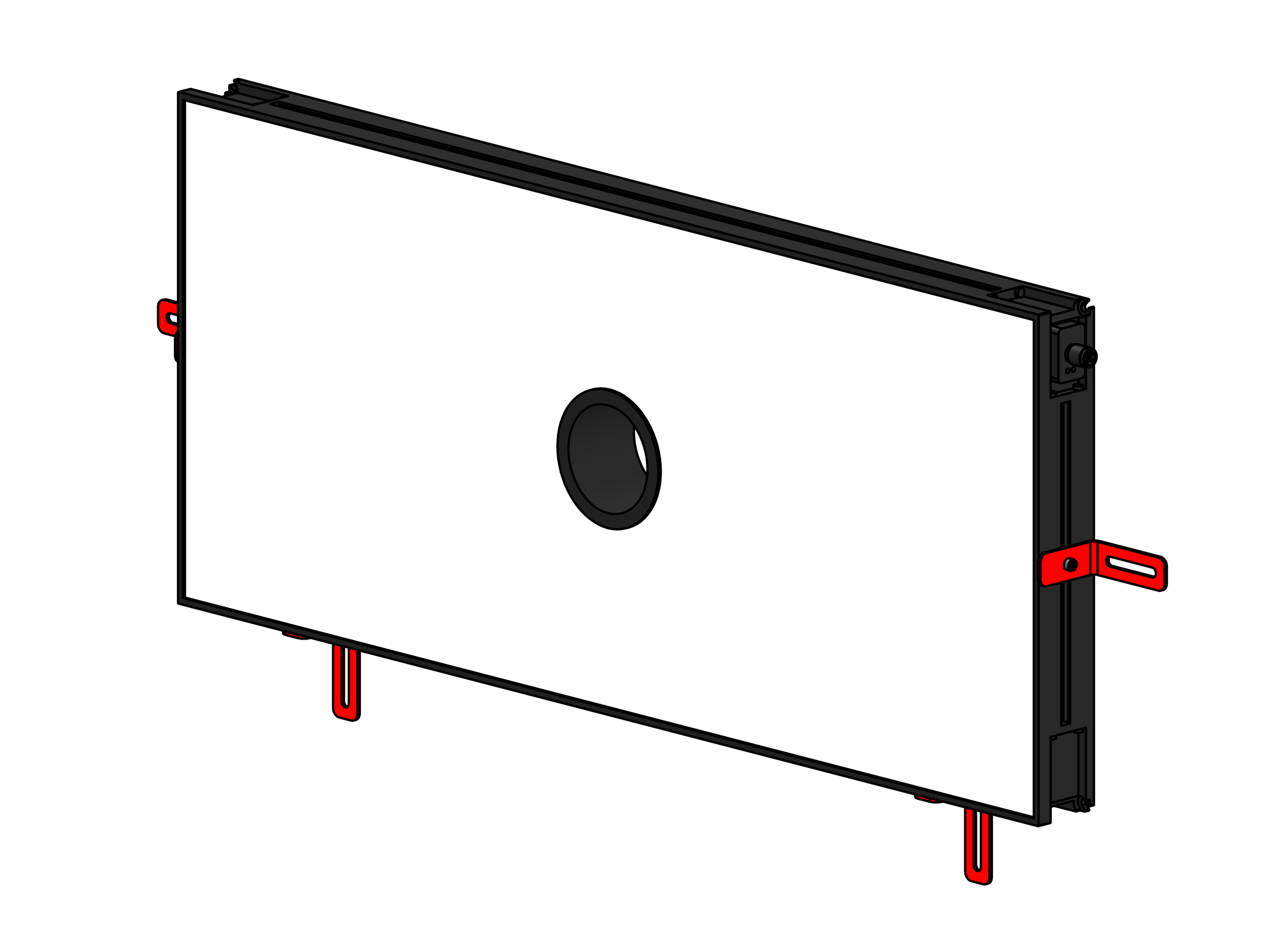
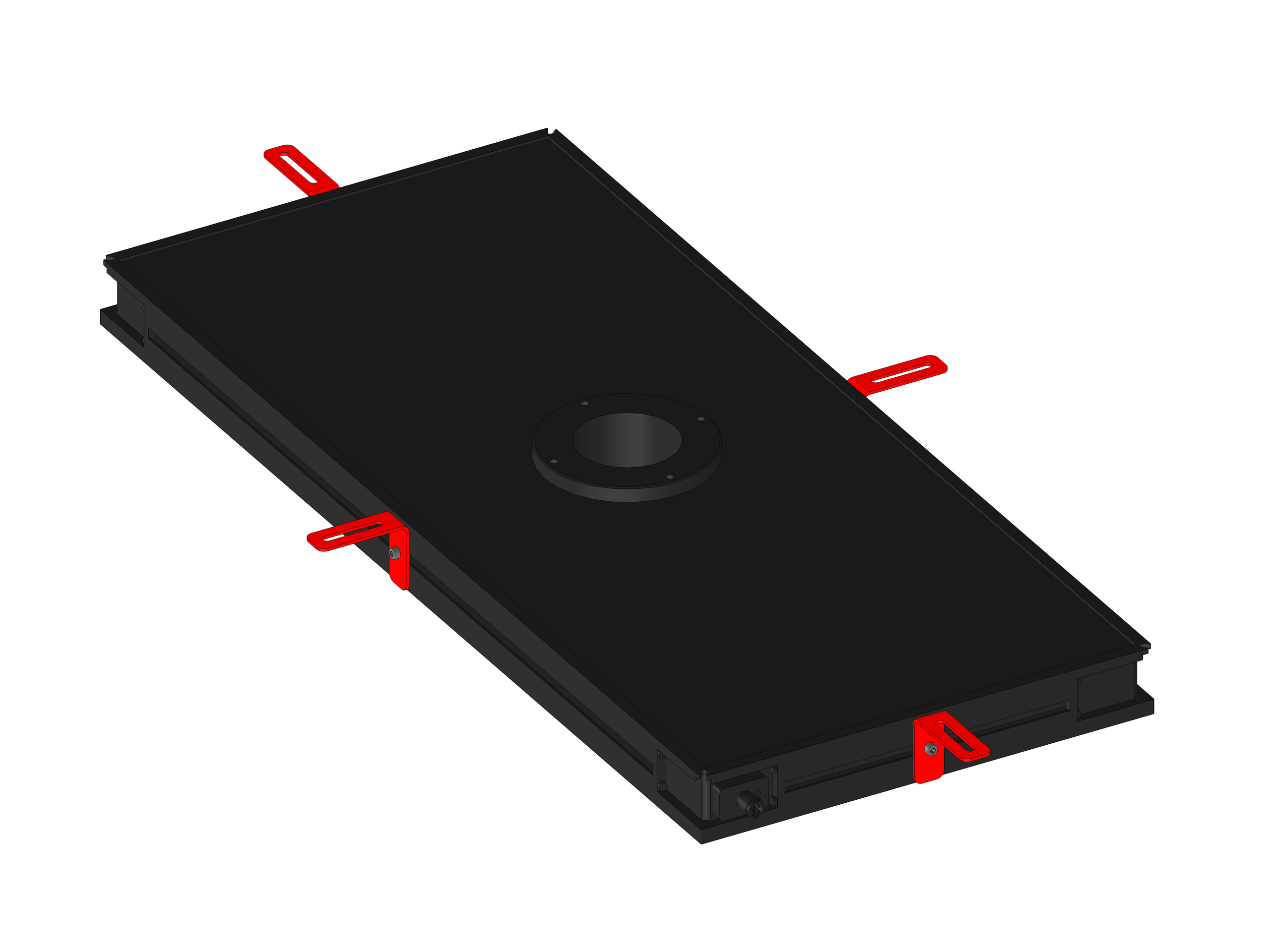
For side mounting, the dedicated bracket can be purchased separately.
Illuminator wiring#
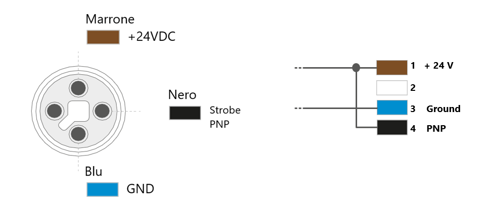
Parameter |
Requirement / Action |
|---|---|
Voltage |
24V DC (±10%). Minimum operating voltage: 20V DC on the light input. |
Connector |
M12 5-pin (T-coding). |
Connector pinout |
Pin 1: +24V (brown) — Pin 3: GND (blue) — Pin 4: STROBE PNP (black) |
STROBE mode (PNP) |
5V to 24V for 100% switch-on. 0V to 1V for 100% switch-off. |
CONTINUOUS mode |
Pin 1 (+24V) and Pin 3 (GND) connected; Pin 4 (PNP) connected to Pin 1. |
Voltage drop (M12 cable, 10m) |
1.15V @ 5A — 2.3V @ 10A — 3.5V @ 15A — 4.6V @ 20A (max 20A) |
Shielding |
Use shielded cables to reduce electromagnetic interference (EMI). |
Warning
Electrical safety
Observe the indicated supply voltages and connection terminals.
Do not modify or disassemble the product.
Do not connect or clean the device while it is live.
Do not look directly at the light source.
Fixing hole layout#
Backlight or Toplight?#
Warning
Impact on part recognition
The choice between backlight and toplight significantly affects recognition:
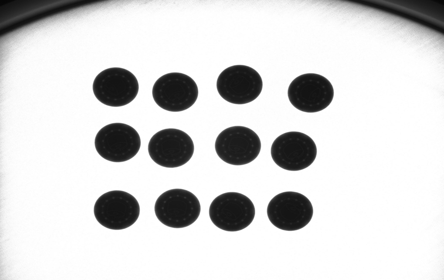
Backlight: Excellent for profiles/outlines; parts appear as dark silhouettes on a light background
Toplight: Required to recognize surface details, textures, internal features
When using an ARS calibration grid, calibration must be performed with the backlight illuminator, and the toplight, if present, must be switched off.
When to use one or the other#
Illuminator |
When to use it |
Example |
|---|---|---|
Toplight |
Used when component recognition cannot be done by the shape alone, but by the details present on the object. It is indicated primarily for smooth, non-reflective surfaces, or surfaces that have some type of distinguishable marking. |
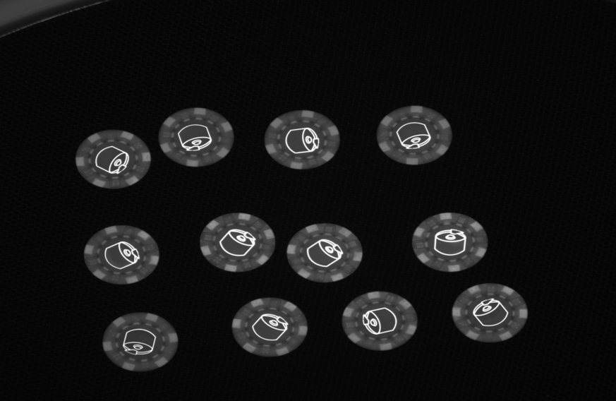
|
Backlight |
The main use case of backlight is when the object can be recognized by its silhouette/shape or with transparent parts. |
|
Typical use cases#
Screws, bolts, washers → Backlight
Parts with printing on the top face, matte parts on dark surfaces → Toplight
Transparent or translucent parts → Backlight
Shiny parts with reflections → Backlight
Lighting Color#
When to use each color#
Color / Wavelength |
Recommended use |
Examples |
|---|---|---|
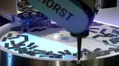
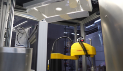
White |
Used with transparent components. The cell must be shielded from any external light source and from sunlight. |
|
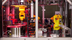
Red (630 nm) |
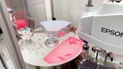
Used for special metal components. Wavelength: 630 nm. The cell must be shielded from any external light source and from sunlight. |
|
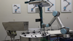
Infrared (850 nm) |
Preferred for most types of applications. Not visible to the human eye. Wavelength: 850 nm. Shielding the cell is recommended to avoid interference from sunlight. |

|
For more information on Ambient Light Shielding, see the Ambient Light Shielding section.
Verifying correct operation of the Backlight and Toplight#
To check that the illuminators are working, simply switch them on from the interface and verify that they light up.
Warning

|
Direct exposure to the light of the illuminators can be harmful to the eyes. Wear suitable protection. |
Note
Infrared illuminators emit invisible light and may therefore appear not to be working. Check them with a camera fitted with an infrared filter to verify that they work. Most smartphones can display infrared.