

Controller and Wiring#
During operation, the machine does not require the continuous presence of an operator.
Attention
Using the machine for a purpose other than that intended by the Manufacturer could cause serious harm to persons and/or property and/or animals. ARS S.r.l. is not liable for damage caused by improper use of the machine.
Controller description#
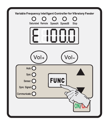
The digital controller (mod. SDVC34-XLRH) is a variable-frequency controller equipped with a microprocessor, LED display and control keypad (Vol+/Vol- buttons for the output voltage, ▲/▼ buttons for the parameters, FUNC key for selection, ON/OFF key for switching on/off and keypad lock).
By default the controller does not generate any output at power-on and remains in the stop state: to enable the main output, a PNP signal must be applied to the Enable Output Port (4-pin connector).
The controller includes automatic protections:
Short circuit → immediate output shutdown, error
Err01Overcurrent → immediate output shutdown, error
Err02Overtemperature → output shutdown above 65 °C, automatic reset below 60 °C, error
Err03
Communication takes place via the RS485 port (Modbus protocol), with a network address that can be set from 1 to 31 and a configurable baud rate.
Controller technical data#
Technical characteristic |
Min |
Typical |
Max |
Unit |
Notes |
|---|---|---|---|---|---|
Input voltage |
85 |
220 |
250 |
V |
AC RMS |
Adjustable output voltage range |
0 |
— |
260 |
V |
Less than 150% of the input voltage |
Voltage regulation accuracy |
— |
1 |
— |
V |
— |
Voltage regulation accuracy (ΔVout/ΔVin) |
0 |
— |
10 |
% |
ΔVout/ΔVin |
Adjustable output current range |
0 |
— |
6 |
A |
— |
Output power |
0 |
— |
1320 |
VA |
— |
Output frequency |
30.0 |
— |
130.0 |
Hz |
— |
Frequency regulation accuracy |
— |
0.1 |
— |
Hz |
— |
Output waveform |
— |
Sinusoidal |
— |
— |
— |
Overtemperature protection trip temperature |
60 |
65 |
65 |
°C |
— |
Digital communication |
— |
ModBus 485 |
— |
— |
— |
Adjustment method |
— |
6 |
— |
Button |
— |
Standby consumption |
— |
7 |
— |
W |
— |
Display method |
— |
5 |
— |
Digit |
LED |
Ambient temperature |
0 |
25 |
40 |
°C |
Non-condensing |
Ambient humidity |
10 |
60 |
85 |
% |
Non-condensing |
Ambient storage temperature |
-20 |
25 |
65 |
°C |
Non-condensing |
Attention
Controllers other than the one supplied by the Manufacturer may be integrated, provided that the Manufacturer has validated their technical characteristics beforehand. ARS s.r.l. is not liable for damage caused by the use of a controller that has not been validated or is not compatible with the machine.
Front panel controls#
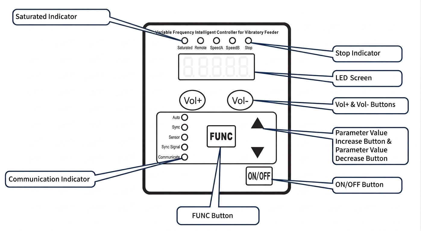
Element |
Function |
|---|---|
LED display |
Shows the current parameter and its value |
Saturated indicator |
Signals saturation of the output signal |
Remote indicator |
Signals that remote control is active |
Speed A / Speed B indicators |
Signal the active speed/output |
Stop indicator |
Signals the stopped state |
Vol+ / Vol- buttons |
Adjust the Common Parameters (see below), at any time |
FUNC button |
Enter/exit and navigate the Basic Parameters |
▲ / ▼ buttons |
Increase/decrease the value of the selected parameter |
Auto / Sync / Sensor / Sync Signal / Communicate indicators |
Operating and RS485 communication status |
ON/OFF button |
Switches the controller on/off |
Rear connectors#
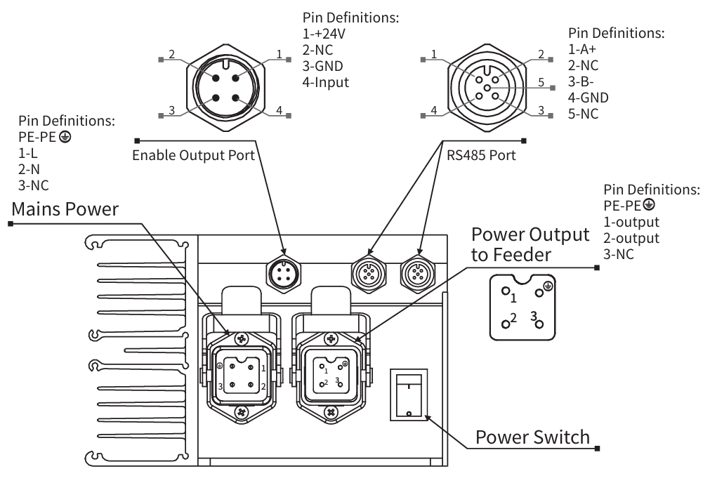
Connector |
Function |
Pinout |
||||||||||||
|---|---|---|---|---|---|---|---|---|---|---|---|---|---|---|
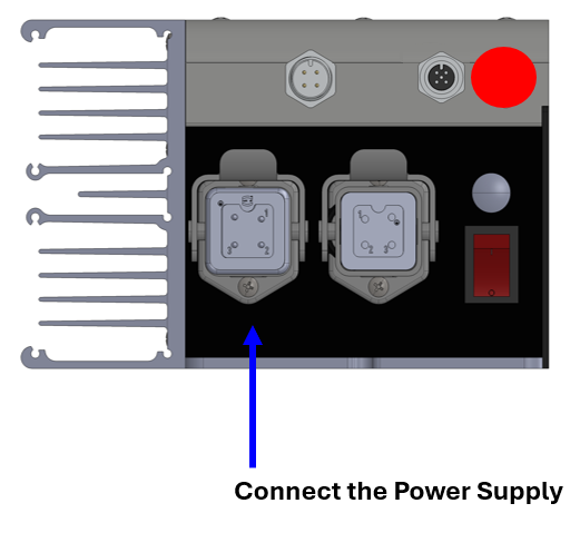
Mains Power (power supply) |
Mains power supply |
Connector pinout
|
||||||||||||
Enable Output Port (4-pin) |
Enable output for external control of the Bulk Feeder, used when it is purchased separately and must be driven by an external device. Cable available as an option: Input cable. |
4-pin connector pinout
|
||||||||||||
RS485 Port (2× 5-pin) |
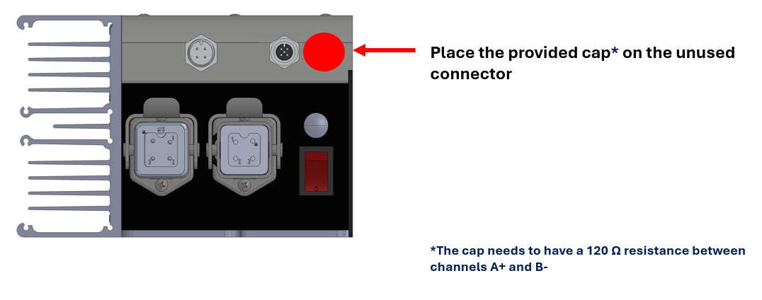
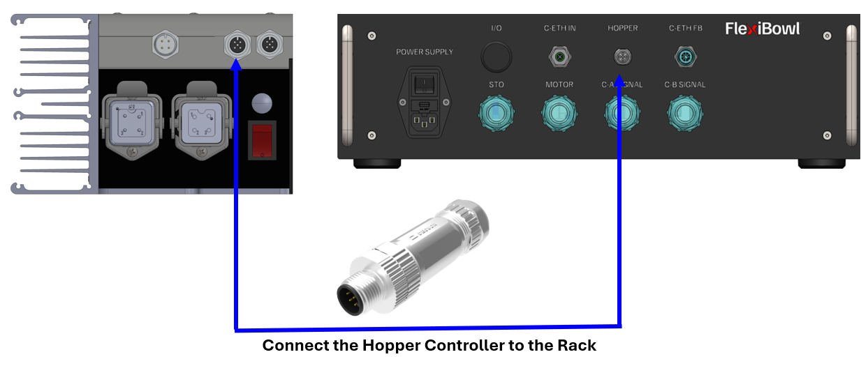
Two identical RS485 connectors: one connects the controller to the FlexiBowl®, the other allows daisy-chain connection between several Bulk Feeders. Cable available as an option: Modbus RTU cable. Important In a single Bulk Feeder configuration, the unused connector must be closed with the dedicated termination plug supplied, fitted with a 120 Ω resistor between A+ and B- |
5-pin connector pinout
|
||||||||||||
Power Output to Feeder (output to the Bulk Feeder) |
Power supply to the Bulk Feeder |
Connector pinout
|
||||||||||||
Power Switch |
On/off switch |
— |
Operating procedures#
Preliminary checks#
Before proceeding with the commissioning of the machine, the following checks must be carried out:
Electrical connection sequence#
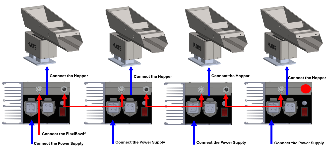
Regardless of the type of controller used (standard, analogue or digital), the electrical connection between Bulk Feeder, controller and FlexiBowl® follows a precise sequence. The sequence differs slightly depending on the model: the FlexiBowl® 500/650/800/1200 have a standard panel with an integrated HOPPER connector, while the FlexiBowl® 200/350 use an external rack with its own HOPPER connector.
FlexiBowl® 500 / 650 / 800 / 1200 — standard panel#
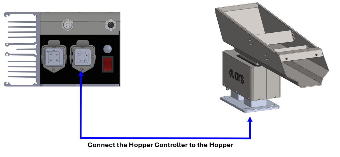
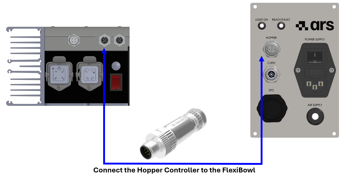
Attention
*The cap must provide a resistance of 120 Ω between the A+ and B- channels.
Important
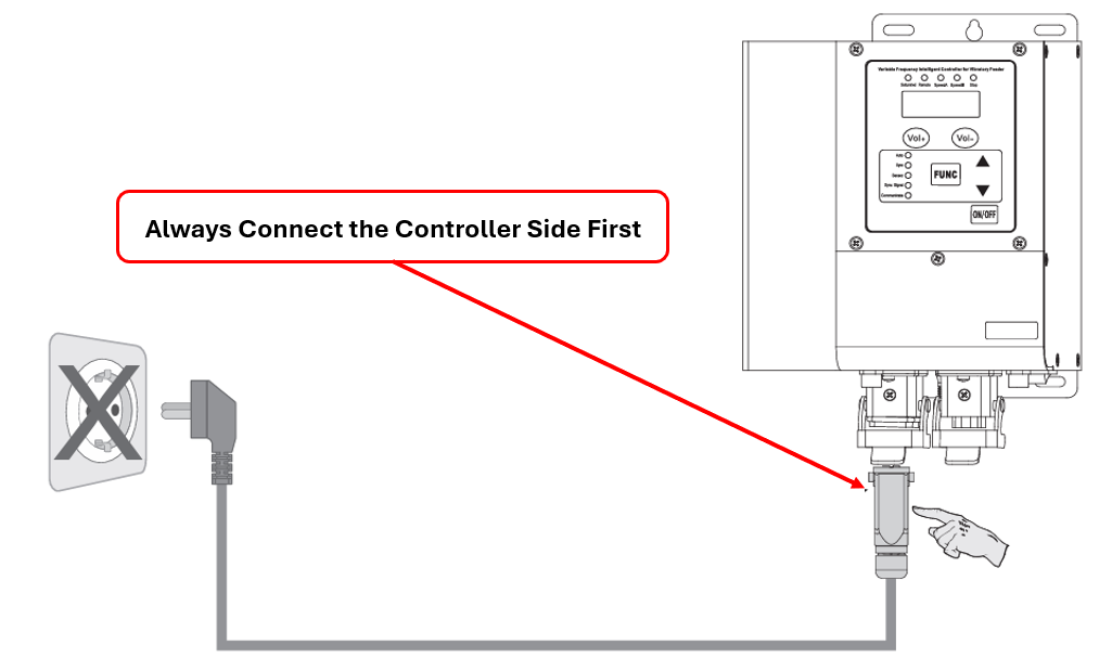
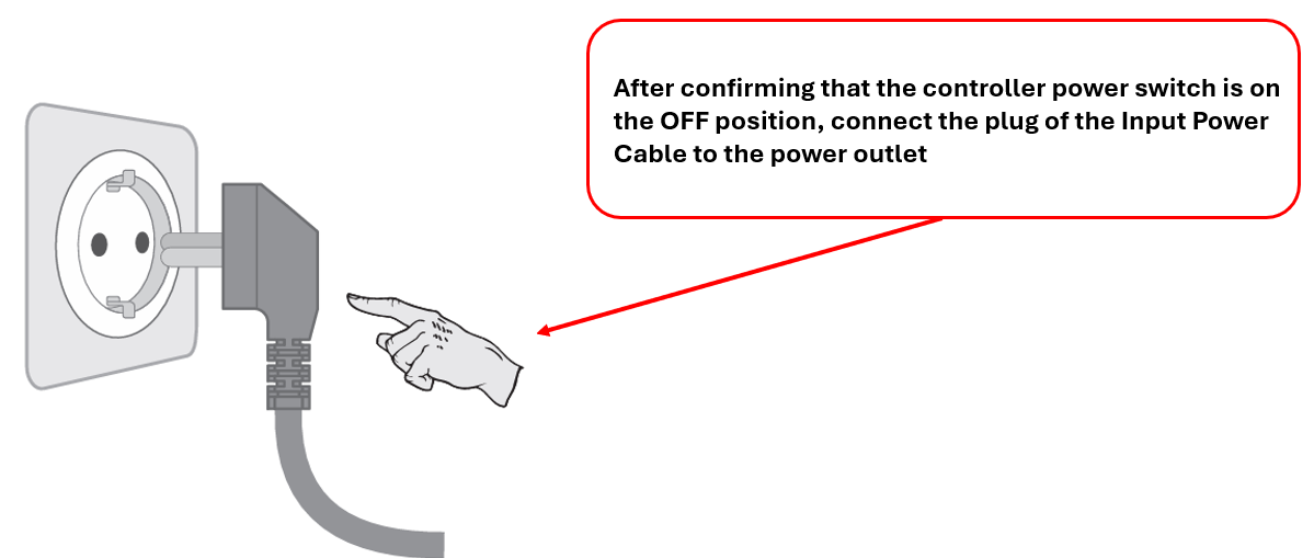
Always connect the controller end of the power cable first, and only then plug it into the socket.
Cascade connection of several Bulk Feeders#
On models with a standard panel, several Hopper Controller units can be connected in cascade, powering each controller individually and connecting the connectors from one unit to the next.
FlexiBowl® 200 / 350 — rack panel#
Attention
*The cap must provide a resistance of 120 Ω between the A+ and B- channels.
Important
Always connect the controller end of the power cable first, and only then plug it into the socket.
Note
Standard controller power supply: 115 Vac or 230 Vac ±5%. Always check that the earth conductor is correctly installed and intact before powering the system.
Setting the communication address#
Once the electrical wiring is complete, the next step is to set a unique communication address on each controller, using the Communication Address parameter (r).
Note
The r parameter represents the controller ID on the RS485 communication network. When several controllers are connected on the same network (e.g. several Bulk Feeders), it is mandatory to assign each one a different address, in the range 1–31, so that they can be distinguished and controlled individually.
Hopper Software Interface#
Once the unique address has been assigned to each controller, the Bulk Feeders are integrated into the FlexiBowl® software and can be controlled directly from its interface, without having to operate the individual controllers manually.
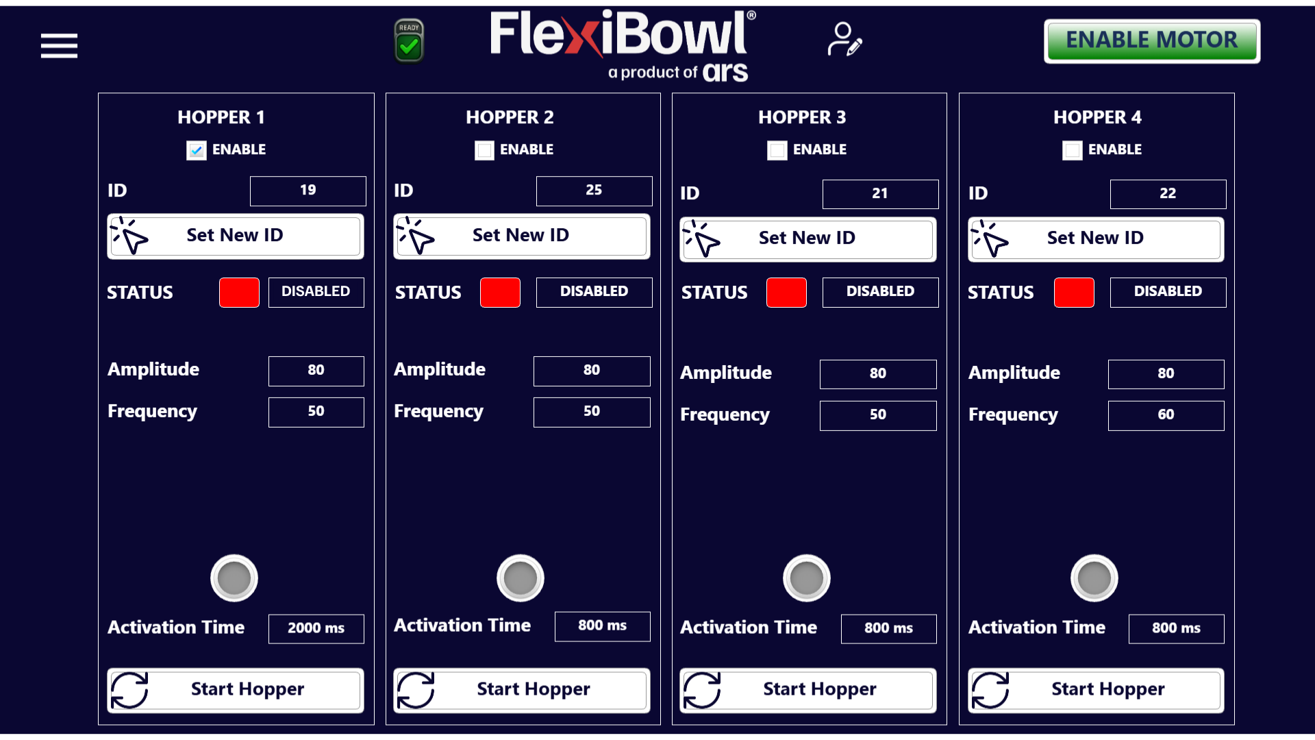
From the software interface it is possible, for each connected Bulk Feeder, to:
Field |
Function |
|---|---|
ID |
Communication address of the controller (must match the one set manually) |
ENABLE |
Enables the Bulk Feeder for operation |
Set New ID |
Assigns a new communication address from the software |
STATUS |
Current status of the Bulk Feeder (e.g. Disabled) |
Amplitude |
Vibration amplitude |
Frequency |
Vibration frequency |
Activation Time |
Bulk Feeder activation time (ms) |
Start Hopper |
Starts the Bulk Feeder manually |
Note
All the adjustments available through the software interface can also be made directly from the controller, using the Common and Basic Parameters described below.
Common Parameters#
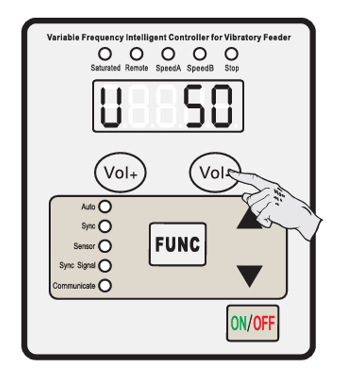
The Common Parameters can be adjusted at any time using the Vol+ / Vol- buttons, even while another parameter is shown on the display: when the adjustment is finished, the controller automatically returns to displaying the previous parameter.
Definition |
Symbol |
Range |
Default |
|---|---|---|---|
Output Voltage |
|
0–260 (V) |
50 |
Basic Parameters#
Definition |
Symbol |
Range |
Default |
|---|---|---|---|
Output Frequency |
|
40.0–200.0 (Hz) |
100.0 |
Max Adjustable Output Voltage |
|
0–260 (V) |
260 |
Communication Address (RS485 address) |
|
1–31 |
1 |
Communication Baud Rate (communication speed) |
|
0.3–115.2 kbps |
115.2 |
Controller Reset |
|
— |
— |
Controller Reset procedure#
Warning
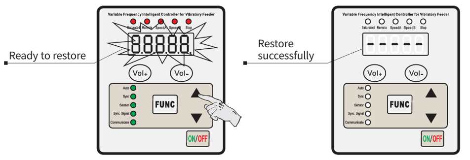
The Controller Reset restores all Common and Basic Parameters to their default values (Output Voltage 50, Output Frequency 100.0 Hz, Max Output Voltage 260, Communication Address 1, Baud Rate 115.2 kbps). Use it with caution if custom configurations are present — in particular the communication address, which will have to be set again.
Commissioning the Bulk Feeder#
Important
If the system includes FlexiVision One, the configuration of the Bulk Feeder parameters is guided in the Bulk Feeder Configuration section.
Otherwise, refer to the Hopper section of this manual.