

FlexiBowl® Wizard#
The FlexiBowl® Wizard interface is an interactive tool designed to guide the user in configuring the feeding parameters according to the specific product family to be handled.
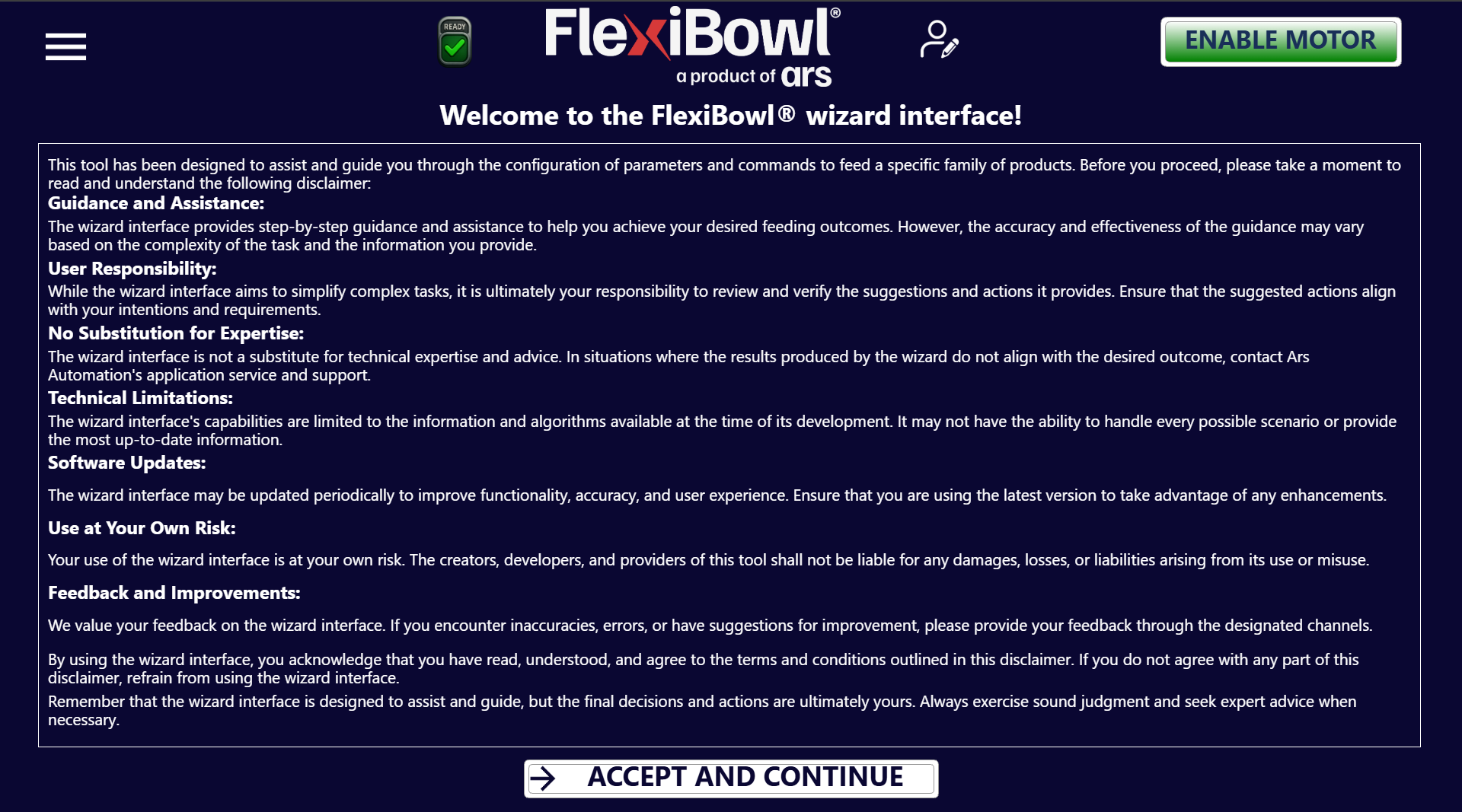
Step 0: Accessing the Wizard#
1 |
To access the guided configuration of the FlexiBowl® parameters, simply click the Wizard page in the side menu. |
Note
The FlexiBowl® model and direction of rotation are detected automatically by the software.
Step 1: Component characterization#
The system requests information on the morphology of the parts in order to optimize separation.
2 |
Select the size of the component: For FlexiBowl 200, 350, 500, 650 models: <= 150mm > 150mm For FlexiBowl 800 and 1200 models: <= 250mm > 250mm |
3 |
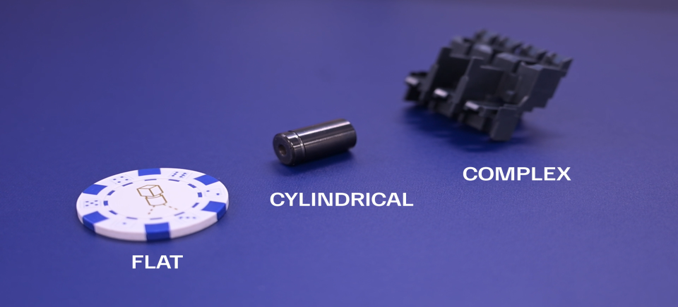
Select the geometry that best describes the component:
Examples of geometries: Flat, Cylindrical and Complex. |
4 |
Define how the components interact with each other on the surface:
Not Overlapping: the parts do not overlap on the surface.
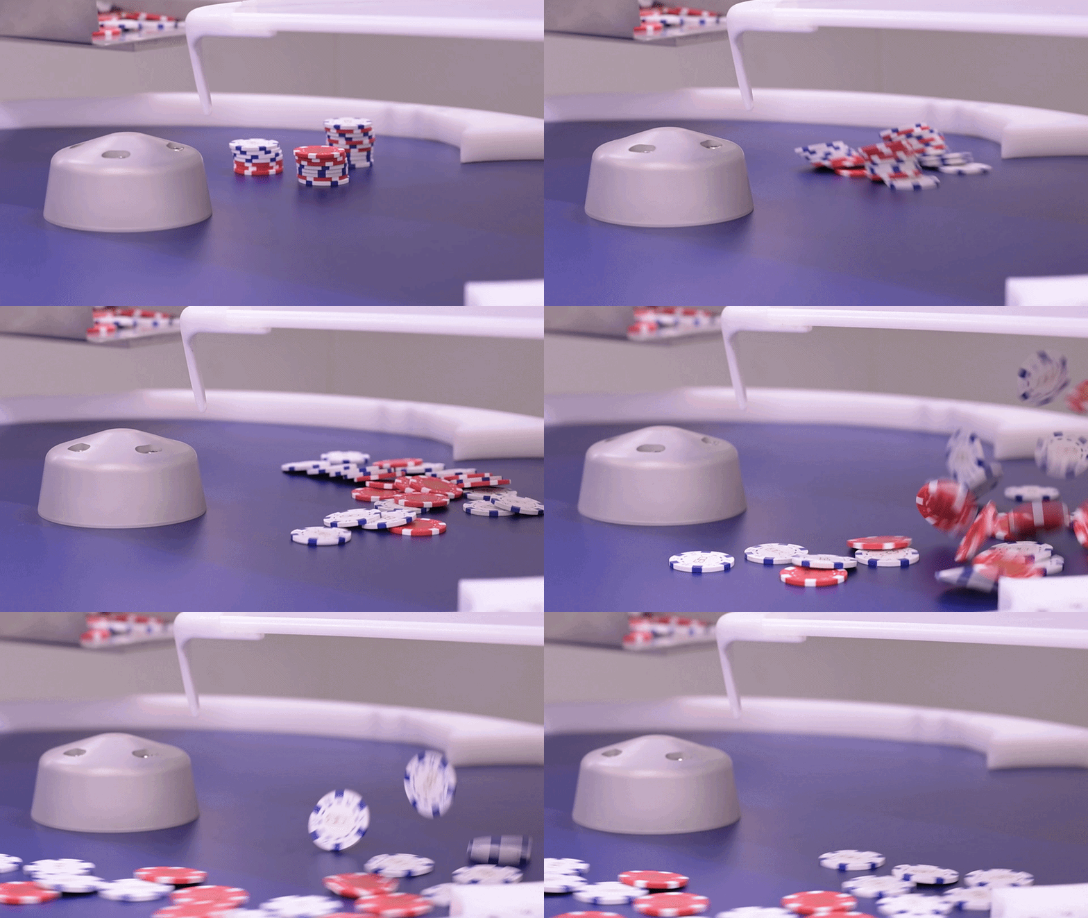
Stacking: the parts stack up.
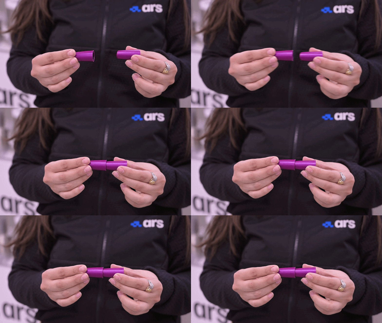
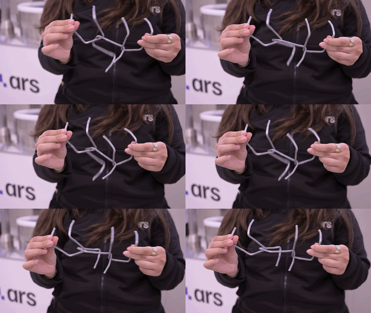
Tangling: the parts hook onto each other. |
Step 2: Accessory test#
5 |
Select from the drop-down menu whether the FlexiBowl® is equipped with the Air-blow module. |
6 |
Click TEST Air-blow to check that it works. |
7 |
Select USE to enable it in the current application, otherwise click DON’T USE. |
8 |
Click TEST FLIP to verify that the striker actually activates. The “Flip” is the unit that generates the mechanical pulse used to turn the parts over, and it is essential for separating, untangling or flipping the components during the feeding cycle. Important If the pulse cannot be felt, check that the compressed air is connected and adjust the mechanical pressure regulator located on the control panel. |
9 |
At the end of the Wizard, click FINISH: the system will automatically calculate the parameters:
|
10 |
From the drop-down menu, select the sequence in which you want to save the calculated parameters. |
11 |
Click UPDATE SEQUENCE to save the parameters in the selected sequence. |
12 |
You can then fine-tune the parameters on the Sequence page. |
Group |
Parameter |
Description |
|---|---|---|
Move |
Accel, Decel, Speed, Angle |
Parameters of the main movement of the disc. |
Option |
Flip Count, Flip Delay, Blow Time |
Management of the activation timings of the accessories. |
Shake |
Accel, Speed, Angle CW/CCW |
Parameters of the shaking vibration (separation). |
Step 3: Sequence validation#
Open the Sequence page and use the TEST SEQUENCE button to verify that the cycle meets the following efficiency criteria:
Synchronization |
The Flip pulse must end at exactly the same instant as the movement (Move) ends. Adjust the Flip Count and Delay values to align them. |
Image stability |
The components must be stationary at the moment the camera captures the image.
|
Positioning of the parts during the sequence |
During the movement, the parts must be conveyed toward the center of the radius of the FlexiBowl® to maximize the effectiveness of the Flip. At the end of the sequence, the parts must be arranged approximately in the center of the vision area. |
Warning
Always click Synchronize Parameters after every manual change to make the changes active in the controller.