

Transport and Installation#
Important
Lifting and handling operations must be carried out exclusively by specialised and trained personnel qualified to perform such activities.
The machine has been designed so that a forklift of adequate capacity is required during the packing, transport and assembly phases. Note that the machine has no dedicated lifting points (for example: eyebolts).
Packaging#
The machine is shipped by ARS s.r.l. from the production plant to the plant of the Customer who uses it.
Standard shipping methods:
Normal protective packaging: Suitable for short and medium distances.
Special protective packaging: Suitable for long distances.
Note
Note on transport: Shipment must be carried out with covered or tarpaulin-covered means of transport, depending on the type of load.
Receiving and unpacking the machine#
On receipt of the machine, the customer must check that there is no damage caused by the transport methods or by the personnel in charge. Follow the procedures below scrupulously:
Leave the packaging concerned in the state in which it was found and immediately request an assessment of the damage by the competent shipping company. Then notify the competent transport insurer and the point of sale of the damage found, with a damage certificate.
If the machine is delivered in a crate on a pallet or wooden brackets with possible heat-shrink cellophane protection, first remove the cover. To free the machine completely, remove the screws and the metal strapping. Then lift the machine with a crane or forklift (as described in the technical data) and remove the pallet used for transport.
Table of groups and weights - with packaging#
Use the following table for weights and dimensions including packaging.
Specification |
Bulk Feeder 1.5 l |
Bulk Feeder 3 l |
Bulk Feeder 5 l |
Bulk Feeder 10 l |
Bulk Feeder 20 l |
Bulk Feeder 40 l |
|---|---|---|---|---|---|---|
Gross weight |
28 kg |
28 kg |
39 kg |
41 kg |
59 kg |
(Verify value) |
Wooden crate dimensions |
700 x 700 x 500 |
700 x 700 x 500 |
700 x 700 x 500 |
700 x 700 x 500 |
1000 x 1000 x 500 |
1000 x 1000 x 500 |
Attention
In the case of custom models the values may differ from those indicated. For such models, refer to the project documentation.
Handling with packaging#
Operator qualification |
Lifting equipment operator |
Required PPE |
|
Lifting equipment |
Forklift with a capacity of not less than 50 kg |




Attention
Use only suitable and approved lifting equipment, compatible with the size and weight of the machine.
Attention
Make sure that no one is standing under or within the operating range of the lifting equipment.
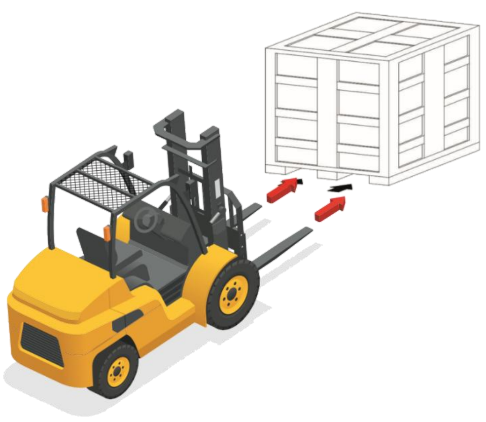
To handle the machine body with its packaging, proceed as described:
Attention
Position the forks of the forklift as shown in the figure.
Removing the packaging#
To remove the packaging, proceed as described:
Attention
For manual lifting of the Bulk Feeder out of the wooden crate, 2 operators are required.
For the handling of the machine and/or its parts, refer to the paragraph “Transport and handling”.
Packaging disposal#
The packaging is an integral part of the supply and is not taken back, so its disposal is the responsibility of the purchaser. Any disposal or destruction must take place in compliance with the regulations in force in the user’s country, taking into account the nature of the materials:
Timber: for the crates;
Plastic film: for protecting the machine, and adhesive tapes for fastening;
Bags of absorbent substance: for protection against moisture;
Other residual items (e.g. straps, nails, etc.).
Transport and Handling#
Depending on the transport method, ARS s.r.l. uses packaging and fastenings suitable for ensuring integrity and preservation during transport.
On receipt of the machine, check that no part has been damaged during transport and/or handling. If anomalies or damage are found, they must be reported to the Manufacturer immediately.
Note
Note on qualifications: The handling activities described in this paragraph must be carried out exclusively by personnel qualified for such operations: personnel specifically trained to carry out loading, unloading and handling operations safely using lifting equipment, and who are aware of the accident-prevention rules.
Attention
Never lift the unit by the tank or the moving part, as, in addition to going out of calibration, it could also suffer deformation or breakage.
Attention
ARS S.r.l. is not liable for damage to property or persons caused by accidents resulting from failure to comply with the instructions given in this manual.
Assembly#
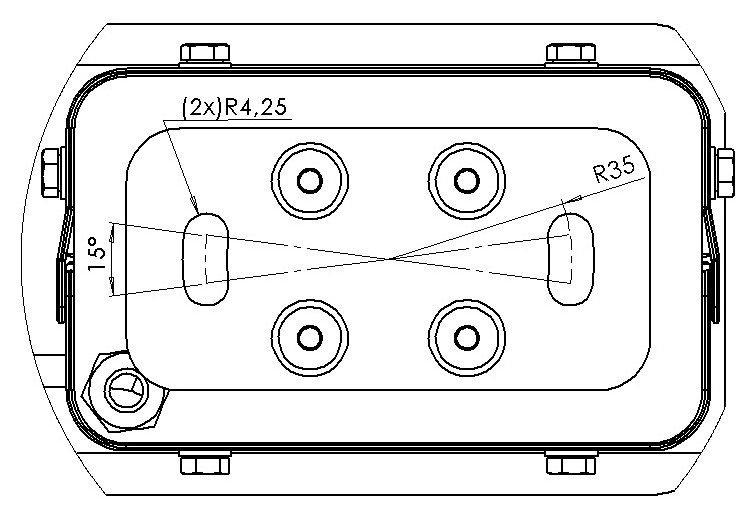
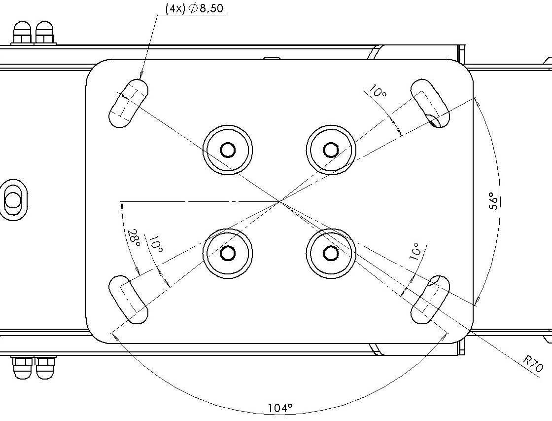
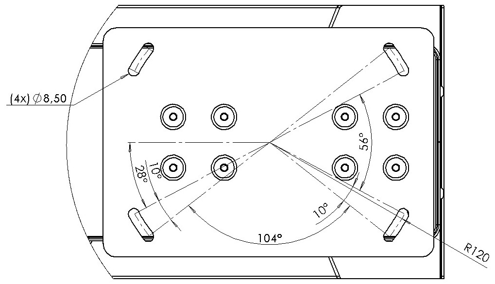
After unpacking, the Bulk Feeder is already assembled. Proceed with fastening it to the following bracket with M8 screws:
Bulk Feeder 1.5 l
Bulk Feeder 3 l
Bulk Feeder 5 l / 10 l / 20 l / 40 l
Attention
In the case of custom models the groups may differ, partially or totally, from the base ones. For such models, refer to the project construction drawing.
Installation#
Provisions at the customer’s expense#
Without prejudice to any different contractual agreements, the Customer is normally responsible for providing:
Note
Note on responsibility: All the technical specifications required are contained in the sales contract. The Manufacturer declines all liability if the customer does not ensure the agreed technical characteristics of the electrical system.
Permitted environmental conditions#
The environment in which the machine is installed and used must be indoors and sheltered from atmospheric agents (rain, hail, snow, fog), airborne or combustible dust, corrosive vapours or sources of excessive heat. The area must not be classified as ATEX.
In particular, the installation and use environment must not present:
Exposure to corrosive fumes or oily vapours;
Exposure to excessive humidity (above 85 %) and rapid changes in relative humidity (above 0.005 p.u./h);
Exposure to excessive or abrasive dust;
Exposure to explosive dust or gas mixtures or to salt-laden air;
Exposure to abnormal vibrations, impacts or shocks;
Exposure to high or rapid temperature changes (above 5K/h) or nuclear radiation.
Environmental operating limits:
Permitted environmental conditions |
Operating values |
|---|---|
Ambient temperature |
5 ÷ 40 °C |
Humidity range |
5 - 90 % (non-condensing) |
Ambient lighting |
Neon light |
Attention
Environmental conditions other than those specified may cause serious damage to the machine. Placing the machine in environments that do not correspond to those indicated voids the warranty for the parts to be replaced.
Important
The work surface must be sufficiently lit. If shadow areas or differences in level are found at the workplace, it is the user’s responsibility to provide suitable lighting devices. If these requirements are not complied with, the Manufacturer declines all liability.
Installation Area#
Attention
Never lift the unit by the moving assembly, as the vibrator has been calibrated at the factory according to your specific requirements and could go out of calibration.
The unit must not be installed where the channel could come into contact with rigid objects or adjacent surfaces; maintain a clearance of about 3-5 cm between the vibrating part and the surrounding static parts.
Bulk Feeders can withstand a specific maximum load. It is essential to size the structural support so that it safely sustains the total weight of the system under vibrating load:
Model |
Maximum permissible load |
Output (t/h) |
|---|---|---|
1.5 l |
1 kg |
0.6 |
3 l |
1.5 kg |
0.6 |
5 l |
6 kg |
2 |
10 l |
6 kg |
2 |
20 l |
6 kg |
2 |
40 l |
15 kg |
5 |
The control unit must be installed as close as possible to the Bulk Feeder, in a dry, clean and vibration-free place.
Positioning the Bulk Feeder#
For correct positioning, follow this operating sequence:
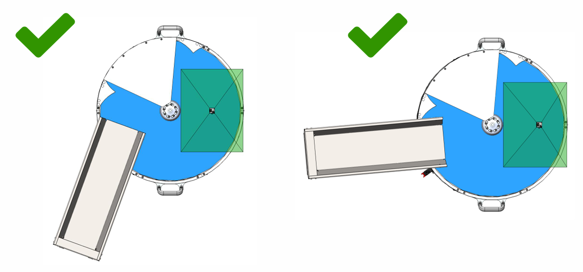
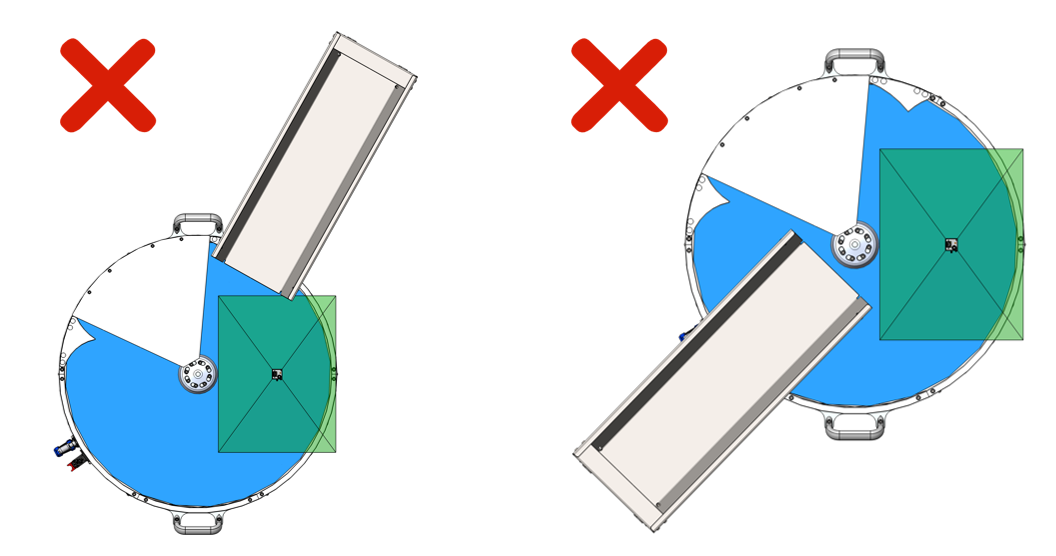
Attention
In the case of custom models, the maximum permissible load and the output may differ from the values indicated. For such models the Manufacturer makes the relevant data available.
Attention
Make sure the machine’s supporting surface is flat and horizontal and suitable for supporting its weight.
Connections#
For the machine to be put into operation, the necessary connections to the local networks must be ensured:
Electrical connection (including the earth connection).
It is the sole responsibility of the user to guarantee the required connection characteristics.
Attention
The required connections must be made by qualified and authorised personnel.
Electrical Connection#
Attention
Before carrying out any electrical connection operation, it is important to check that the machine is switched off.
Attention
Make sure the customer’s electrical supply line has been isolated beforehand.
The compliance of the connection between the machine and the earthing system is entirely the responsibility and burden of the purchaser.
Attention
The operation must be carried out exclusively by specialised and authorised personnel (electrical maintenance technician).
Before proceeding with the electrical connection, check that:
The technician is aware of the regulations in force in the country of installation;
The frequency and supply voltage values correspond to those of the local network;
The cross-section of the electrical cables used is adequate for the current draw and maximum loads of the machine;
The earthing of the circuit is fully compliant with the EN 60204-1 standards;
The materials used in the earthing system have adequate strength or mechanical protection.
Attention
Do not work with wet hands or objects. In the event of fire, do not use water on electrical components.
Operator qualification |
Electrical maintenance technician |
Required PPE |
|
To connect to the AC electrical mains, proceed as described below:
Important
The standard power supply is 115 VAC or 230 VAC +/-5% (the 115 VAC variant is supplied only on explicit request).
Attention
An incorrect power supply can cause serious electronic faults in the system and prevent it from operating correctly.