

Replacing relays and fuses#
This section describes the operation and the replacement procedure of the interface relays and the protection fuses located on the interface board.
The following figure shows the board with the position of the relays and fuses indicated.
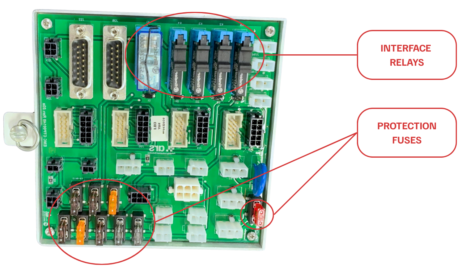
Front view of the interface board#
The rear of the board shows the amperage of each fuse and the reference of each interface relay.
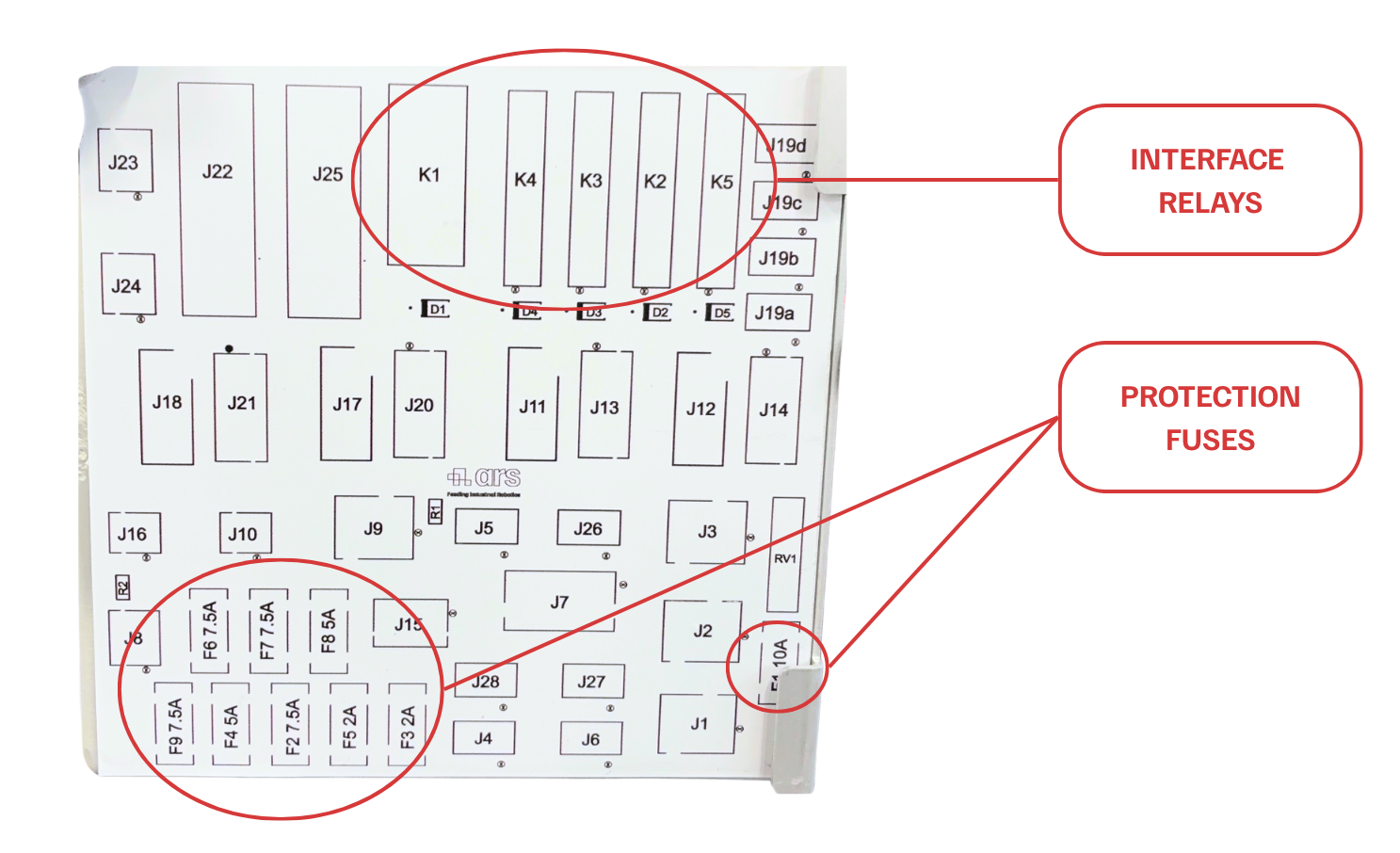
Rear view: relay references and fuse ratings#
Safety warnings#
Danger
Electrical hazard. Before working on the interface board, remove power from the machine using the main switch and wait for the capacitors to discharge. Verify the absence of voltage with a suitable measuring instrument before touching any component.
During maintenance operations, strictly observe the following instructions:
the work must be carried out exclusively by qualified and trained technical personnel;
use suitable personal protective equipment (PPE), including antistatic gloves;
avoid dropping tools or foreign objects onto the board during the work;
do not replace a fuse with one of a different amperage from the original;
do not force the relays during removal: if a component is stuck, check that it is correctly engaged before proceeding;
at the end of the work, close the access door/slot properly before restoring power.
Board description#
Interface relays#
The board is equipped with five interface relays, identified by the designations K1–K5. Relay K1 is a double-pole electromechanical relay; all the other relays (K2–K5) are solid-state relays.
Ref. |
Function |
Type |
|---|---|---|
K1 |
Interface relay for backlight |
Double-pole electromechanical |
K2 |
Interface relay for flip solenoid valve |
Solid state |
K3 |
Interface relay for central blow solenoid valve |
Solid state |
K4 |
Interface relay for radial blow solenoid valve |
Solid state |
K5 |
Interface relay for emptying solenoid valve (optional) |
Solid state |
Protection fuses#
The board is equipped with nine protection fuses of the automotive mini type. The spare fuse kit is supplied with the FlexiBowl®.
Ref. |
Function |
Rating |
|---|---|---|
F1 |
Main power supply |
10 A |
F2 |
24 V supply — flip, central/radial blow and emptying solenoid valves |
7.5 A |
F3 |
STO connector supply |
2 A |
F4 |
Supply to customer |
5 A |
F5 |
Emptying sensor |
2 A |
F6 |
Backlight supply |
7.5 A |
F7 |
Backlight supply |
7.5 A |
F8 |
Motor and driver supply |
5 A |
F9 |
PLC supply |
7.5 A |
Required equipment#
Automotive mini fuse puller (or flat-nose tweezers)
Spare fuse kit supplied with the FlexiBowl®
Spare relays matching the original reference (K1–K5)
Replacing the interface relays#
The procedure applies to the replacement of one or more interface relays (K1–K5).
Remove power from the machine and verify the absence of voltage with the multimeter, as indicated in the safety warnings.
Access the interface board through the dedicated opening.
Locate the relay to be replaced by referring to the rear view and the relay table.
If the relay to be replaced is K1 (electromechanical), gently pull it out of its socket by pulling upwards without forcing the terminals.
If the relay to be replaced is K2, K3, K4 or K5 (solid state), remove it with the same care, avoiding bending the contact pins.
Insert the spare relay into the socket, checking that the reference and orientation match exactly those of the removed component.
Check that the relay is correctly inserted and stable in the socket.
Close the board access opening again.
Restore the power supply and check that the function associated with the replaced relay works correctly.
Replacing the protection fuses#
The procedure applies to the replacement of one or more protection fuses (F1–F9).
Remove power from the machine and verify the absence of voltage with the multimeter, as indicated in the safety warnings.
Open the dedicated access slot to the protection fuses.
Locate the fuse to be replaced by referring to the rear view and the fuse table.
Remove the fuse using the dedicated puller (or tweezers), gripping it without touching the metal parts.
If possible, determine the cause of the fuse blowing before proceeding with the replacement.
Take from the spare kit an automotive mini fuse of the same rating (amperage) indicated in the table.
Insert the new fuse into its seat, checking that it is correctly seated.
Close the access slot again.
Restore the power supply and check that the circuit protected by the replaced fuse works correctly.
Caution
Never use a fuse of a different rating from the original.
Periodic checks and preventive maintenance#
Periodically check for signs of overheating or blackening on relays, fuses and sockets.
Check that the connectors on the board are correctly plugged in.
Always keep a stock of the spare fuse kit available.
Record every replacement carried out (date, component reference, cause) in a maintenance log.