

Electrical Interface#
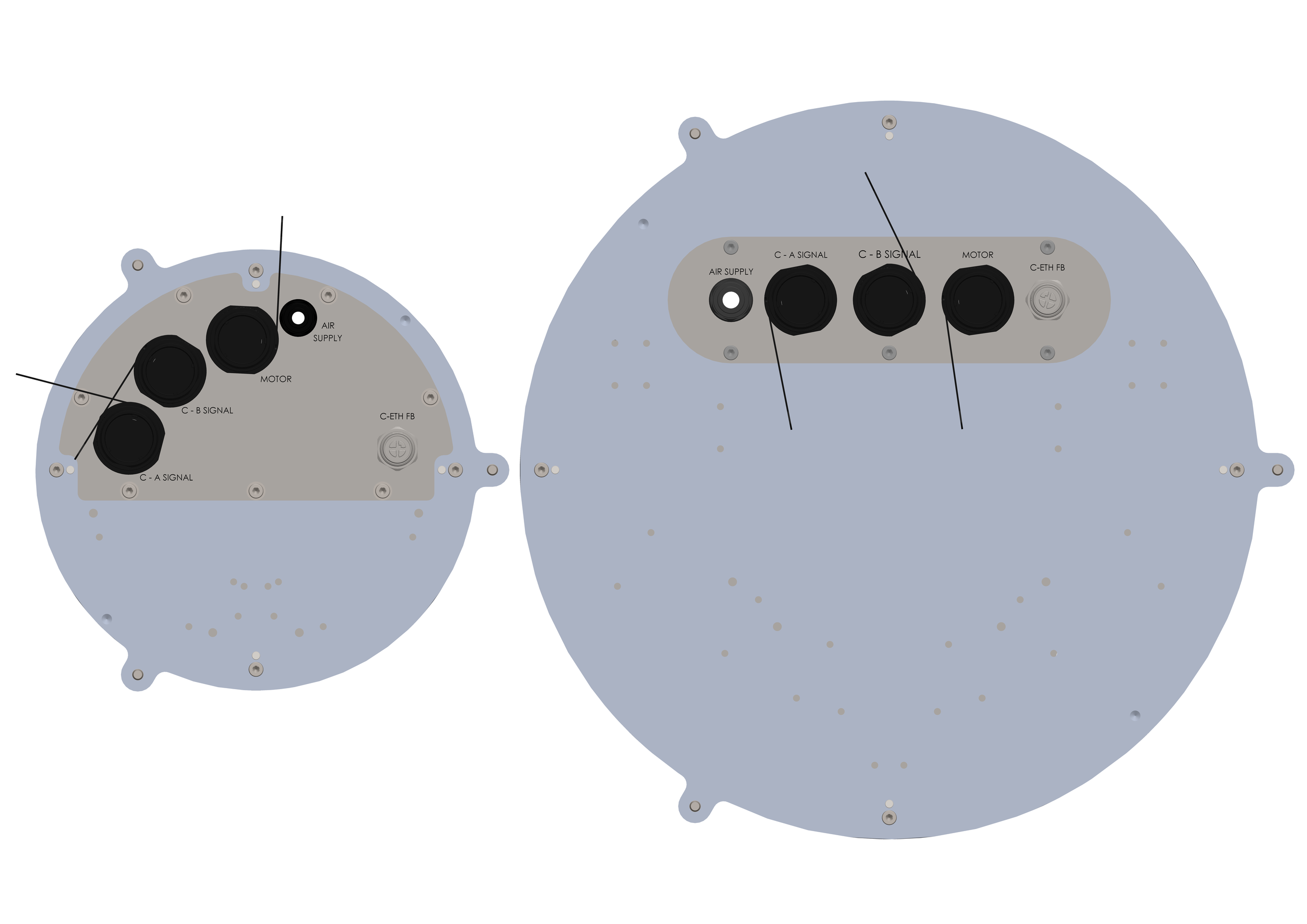
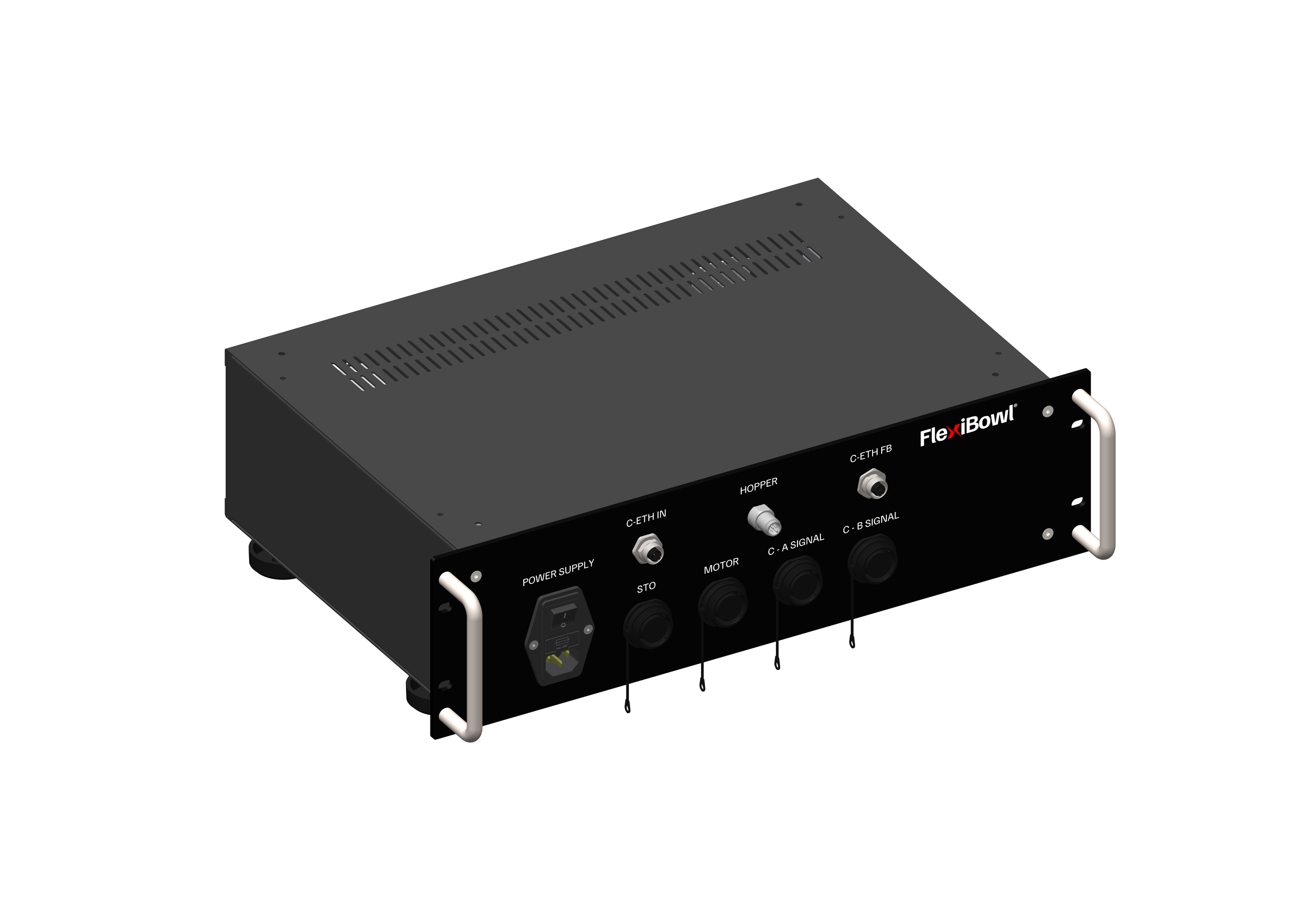
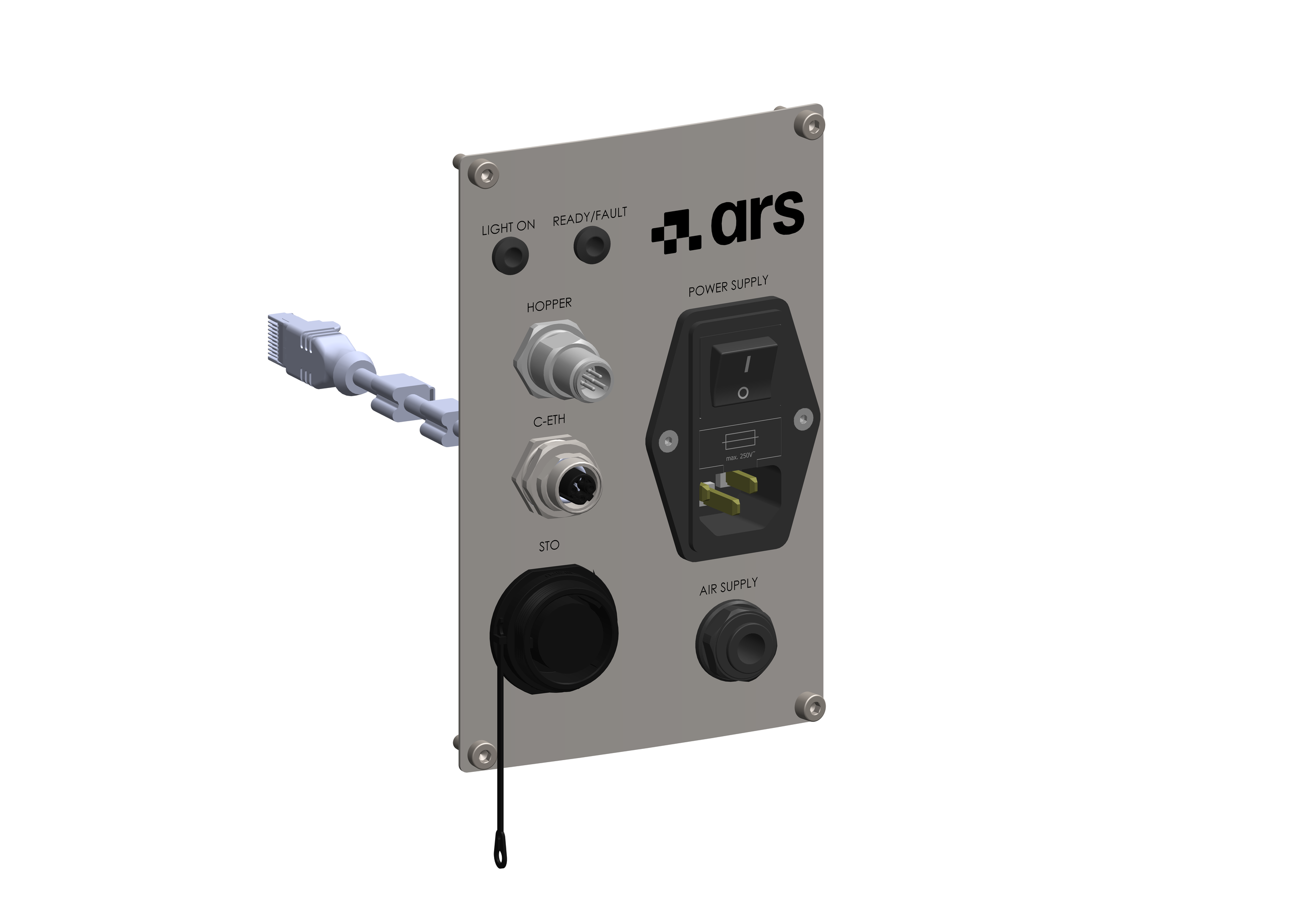
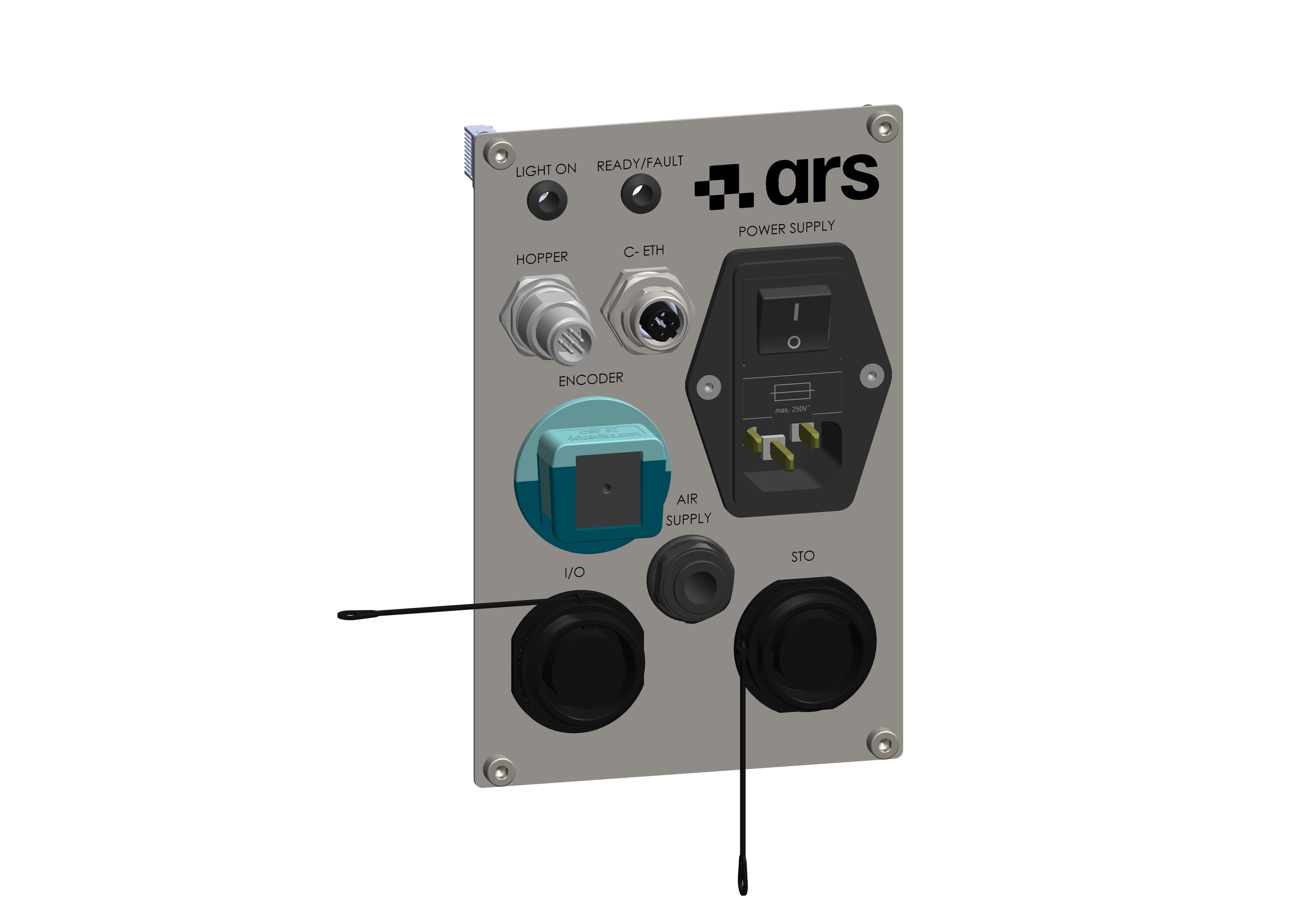
The FlexiBowl® connector panel varies depending on the machine version:
Warning
Before making any electrical connection, make sure that the power supply is disconnected and that the system is in a safe state.
Important
Leave about 100 mm of free space around the power connectors to facilitate wiring and maintenance operations.
The electrical interface of the FlexiBowl® changes depending on the size of the machine:
FlexiBowl® 500 – 1200: all connectors (STO, Ethernet, Hopper, power supply, air) are located on a single standard electrical panel, mounted directly on the machine.
FlexiBowl® 200 / 350: the main connectors are located on an external rack; the rack is then connected to the machine via 4 dedicated cables (Ethernet, Motor+STO, signal A, signal B). Only the compressed air remains to be connected on the machine.
FlexiBowl® 500 – 1200 — Standard Electrical Panel#
Action |
Image |
|||||||||||||||||||||||||||||||||||||||||||||||||||||||||
|---|---|---|---|---|---|---|---|---|---|---|---|---|---|---|---|---|---|---|---|---|---|---|---|---|---|---|---|---|---|---|---|---|---|---|---|---|---|---|---|---|---|---|---|---|---|---|---|---|---|---|---|---|---|---|---|---|---|---|
1 |
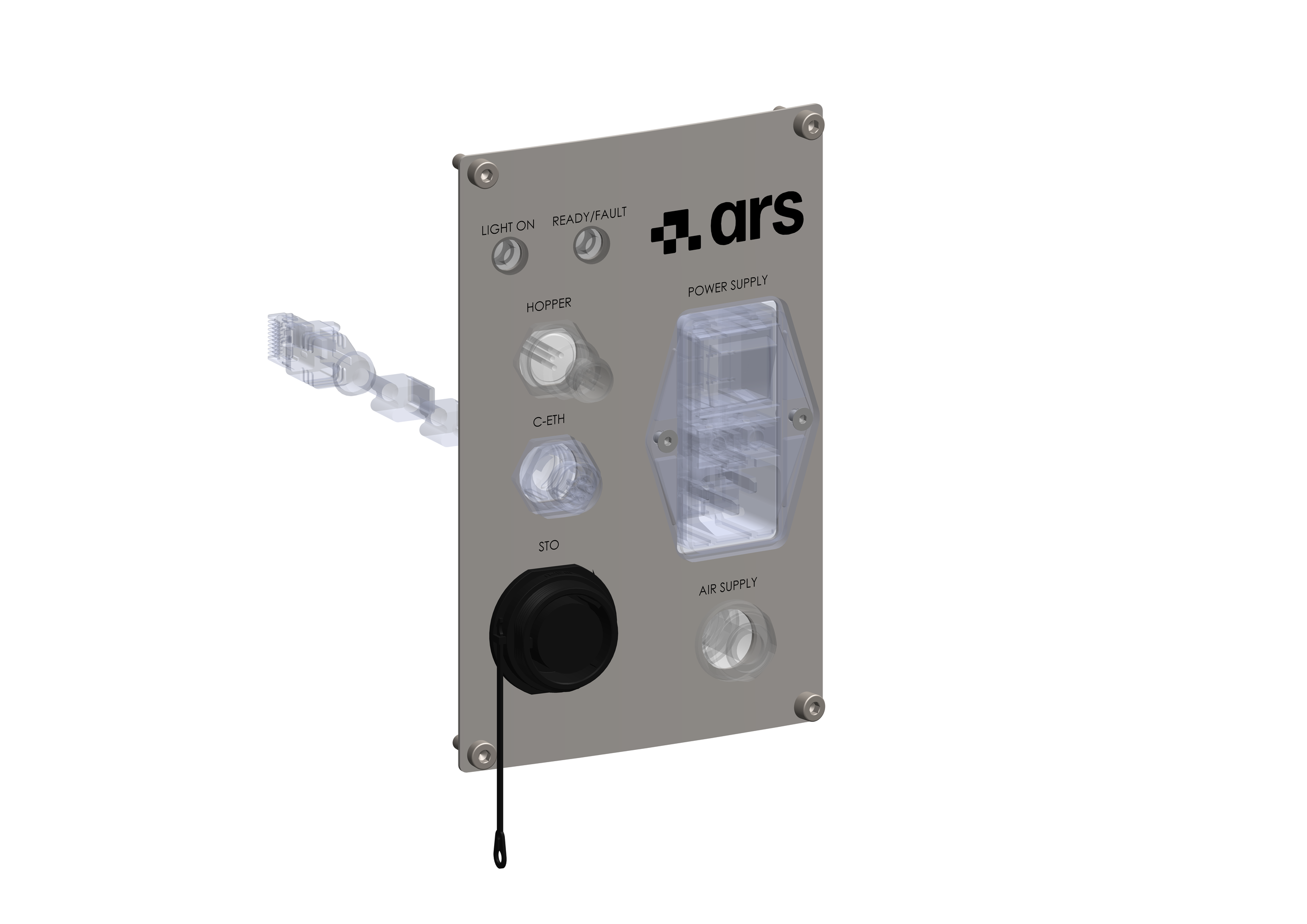
Connect the STO. 10-pin connector. Required to enable the motor.
The +STO1 and +STO2 inputs must receive +24 Vdc from the safety circuit; −STO1 and −STO2 must be connected to the −24 Vdc reference.
STO connector pinout (10 pin)
|
|
||||||||||||||||||||||||||||||||||||||||||||||||||||||||
2 |
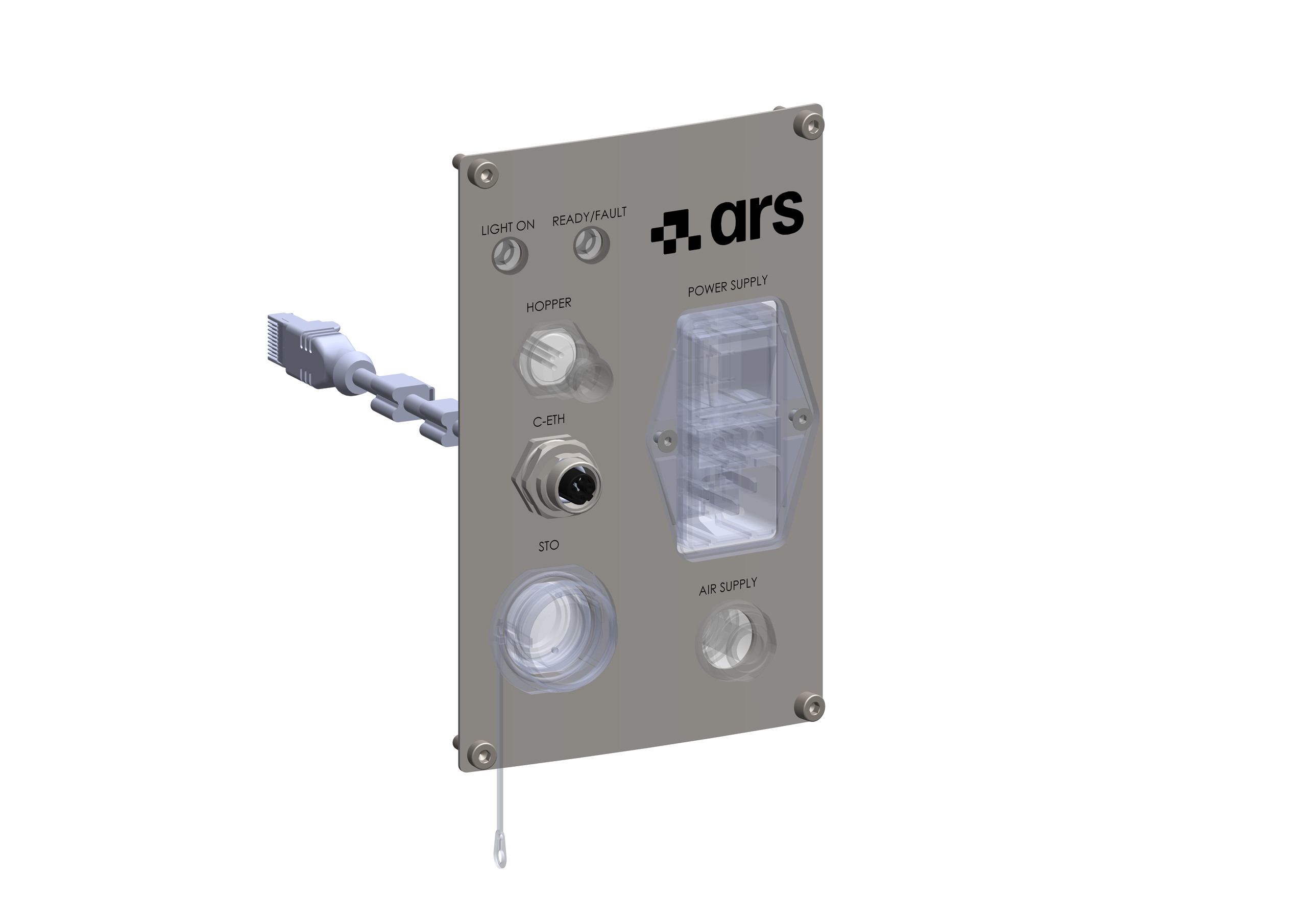
Connect the Ethernet (C-ETH). M12 connector, D-Code coding. It allows communication with the FlexiBowl®, which can also be accessed via web browser.
When the FlexiBowl® is powered, the Ethernet connection is mandatory: if absent, the machine enters the ERROR state (red Ready/Fault LED).
M12 → RJ45 pinout8-pole M12 → RJ45 adapter:
4-pole M12 D-code connector:
|
|
||||||||||||||||||||||||||||||||||||||||||||||||||||||||
3 |
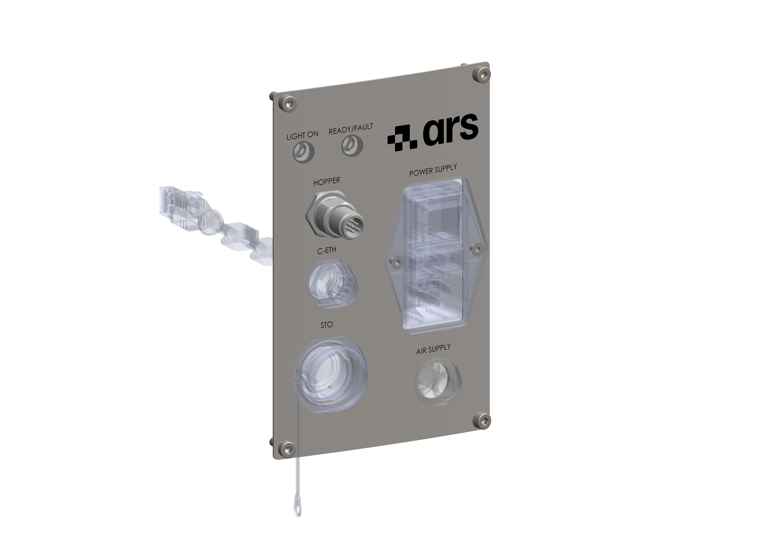
Connect the Hopper. M12 A-code connector, used to communicate with ARS hopper controllers via Modbus RTU protocol. M12 A-code pinout
|
|
||||||||||||||||||||||||||||||||||||||||||||||||||||||||
4 |
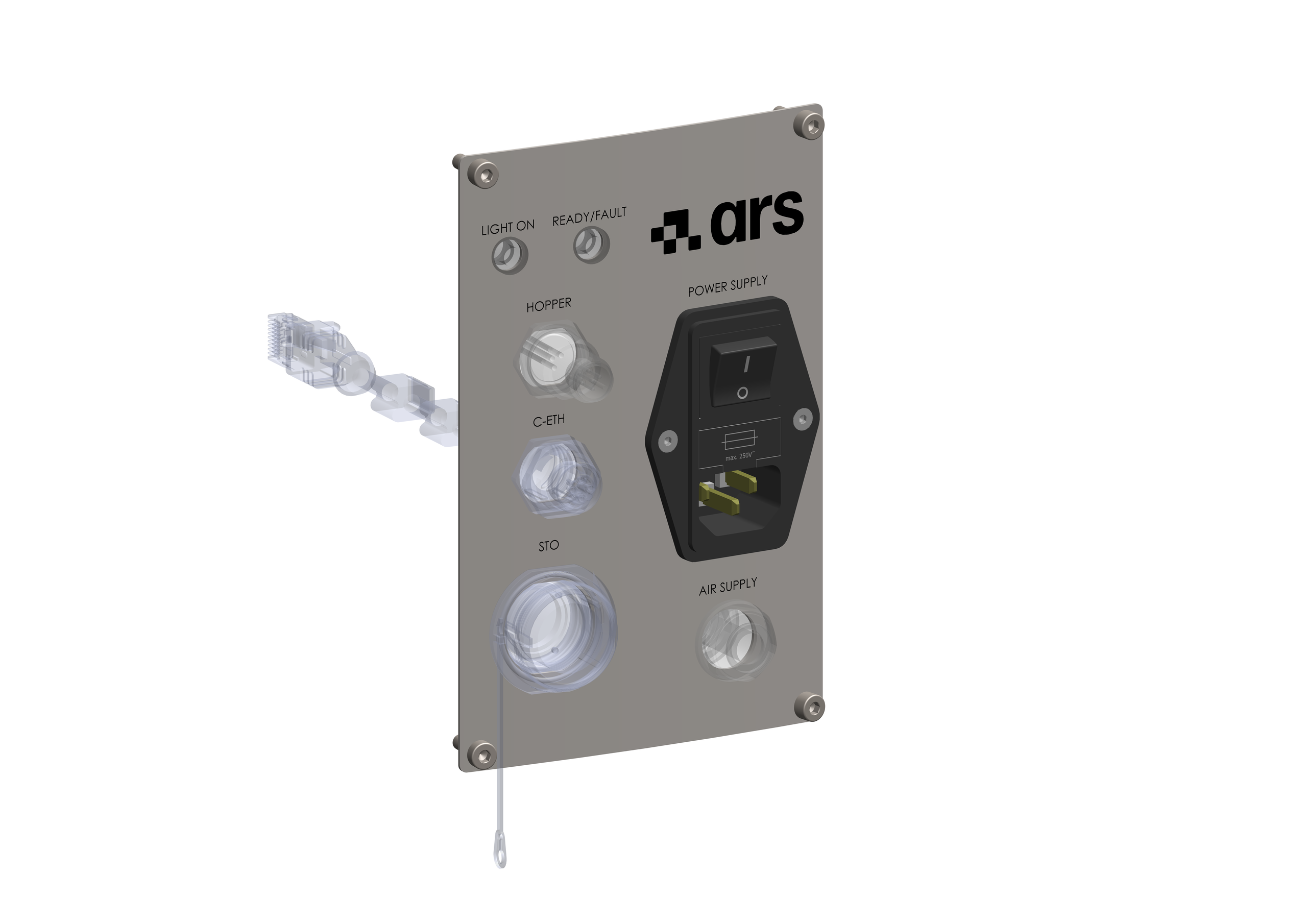
Connect the power supply (Power Supply) — last. Connector supplied with the unit, identified by the label POWER SUPPLY. The power button allows the device to be switched on/off.
Make sure the FlexiBowl® is switched off before connecting the power supply, and that the device is earthed.
Permitted voltage: 120–230 Vac, 50/60 Hz.
The power connector is equipped with a holder for 2 fuses, which protect against possible electrical faults. At first start-up, always check their condition before switching on the device.
Power cable pinout diagram
|
|
Note
After power-up, always check the state of the machine via the status LEDs on the front panel — see the Status LEDs section further down on this page.
Tip
The power and Ethernet cables are available as an option in lengths of 3, 5 and 10 m: see Power supply cable and Ethernet cable.
FlexiBowl® 200 / 350 — External Rack#
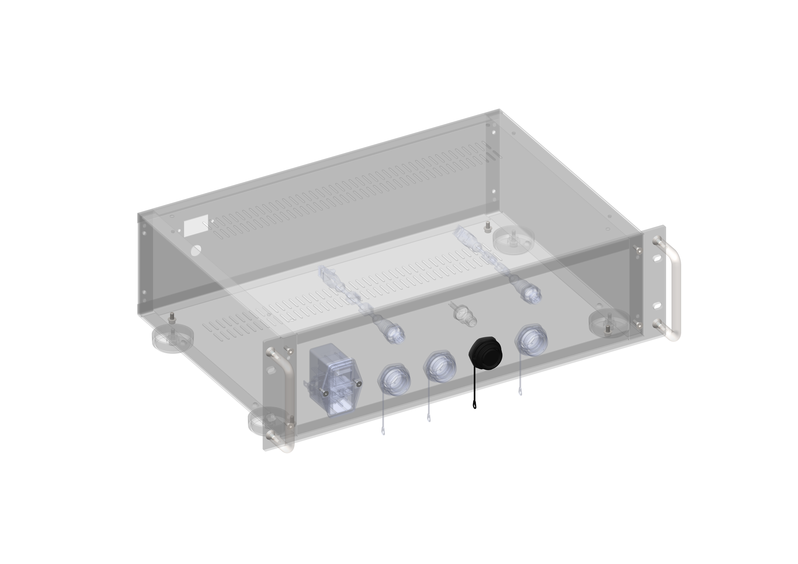
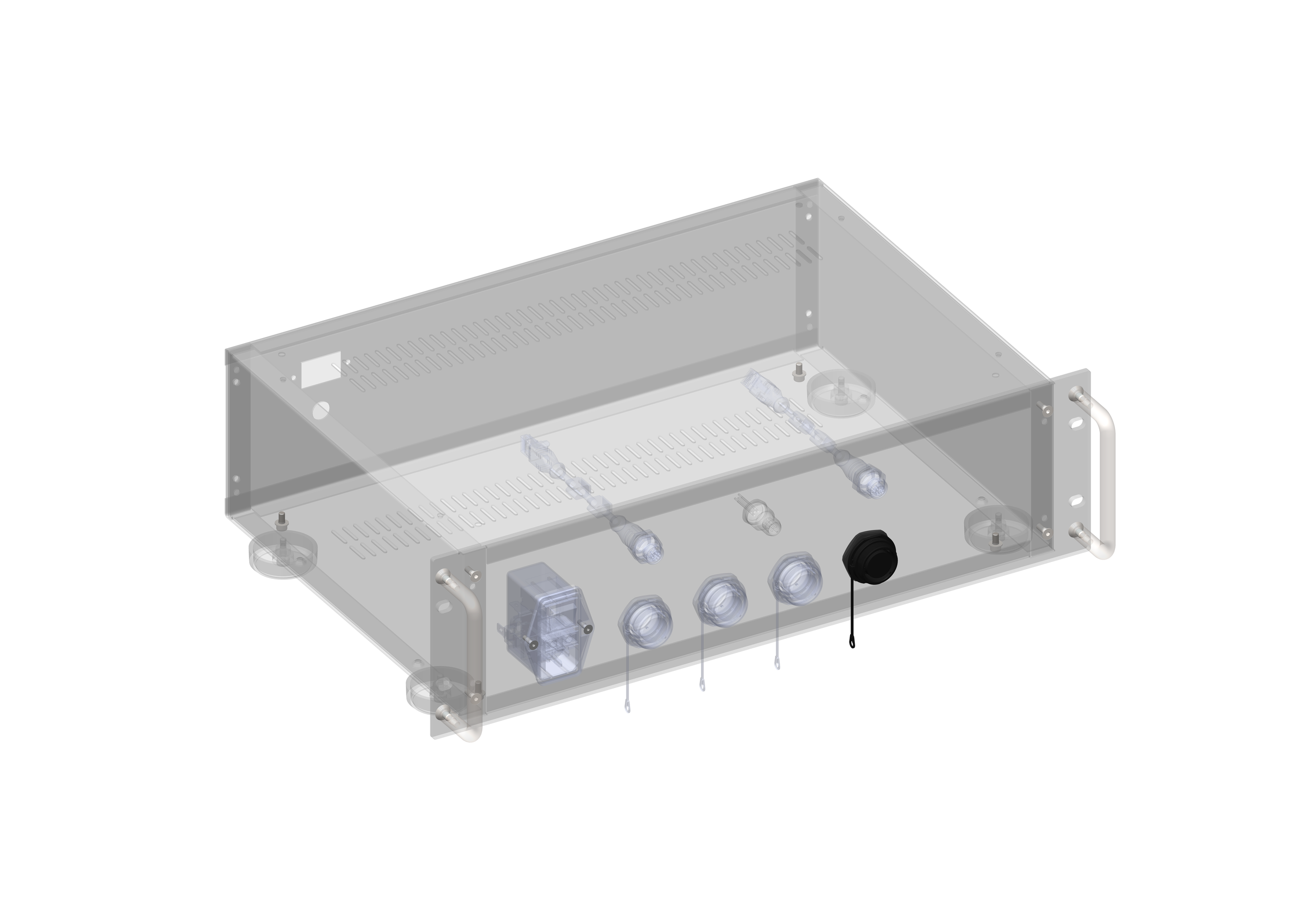
The FlexiBowl® FB 200 and FB 350 models are equipped with an external Rack, containing all the electronic devices needed for operation. The connectors to the customer’s systems are located on the rack (not on the machine) and have the same pinout as the corresponding connectors of the standard panel, simply placed on an external box.
Rack connections#
Action |
Image |
|||||||||||||||||||||||||||||||||||||||||||||||||||||||||
|---|---|---|---|---|---|---|---|---|---|---|---|---|---|---|---|---|---|---|---|---|---|---|---|---|---|---|---|---|---|---|---|---|---|---|---|---|---|---|---|---|---|---|---|---|---|---|---|---|---|---|---|---|---|---|---|---|---|---|
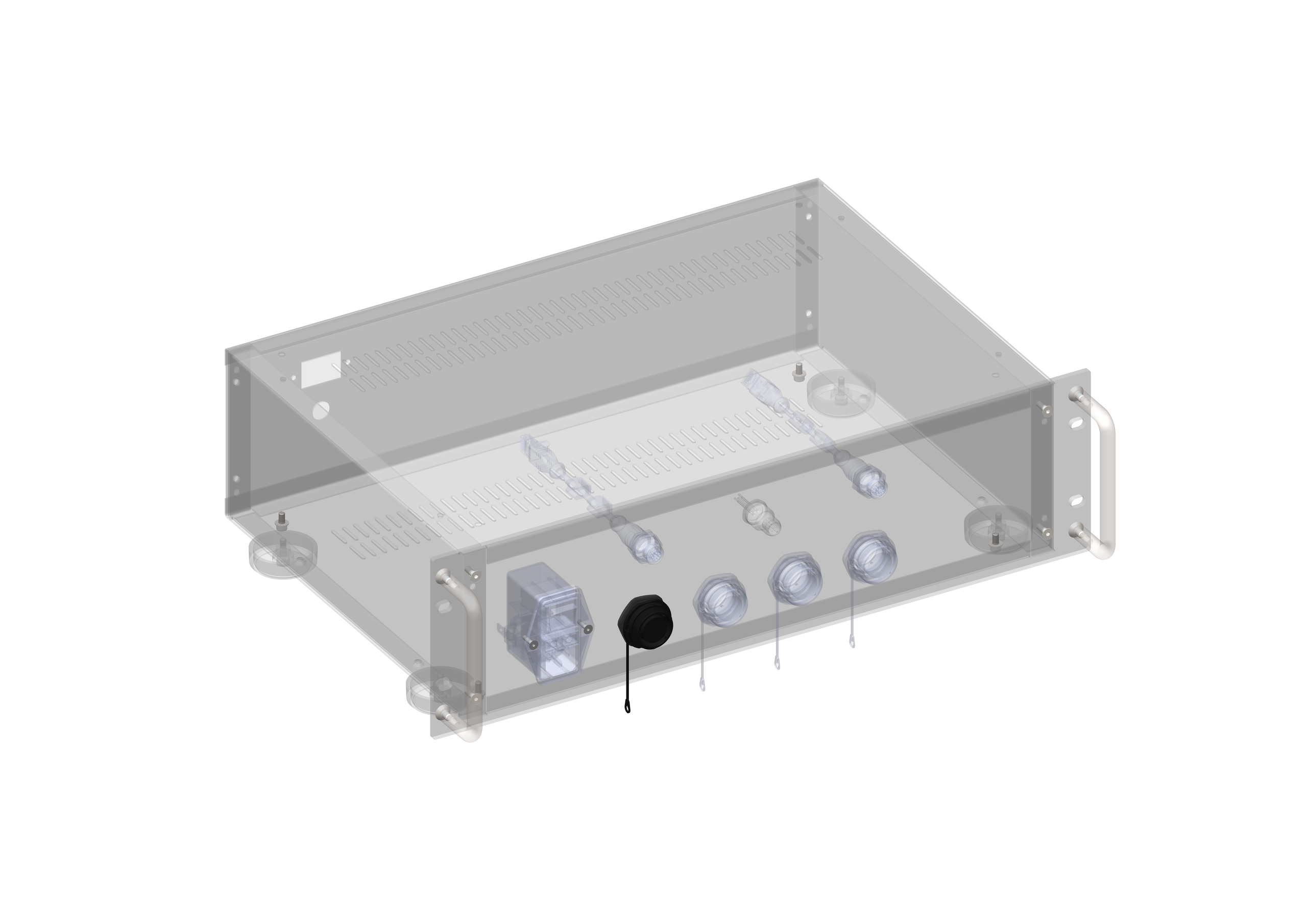
1 |
Connect the STO on the rack. 10-pin connector, same function and pinout as the standard panel.
The +STO1 and +STO2 inputs must receive +24 Vdc from the safety circuit; −STO1 and −STO2 must be connected to the −24 Vdc reference.
STO connector pinout (10 pin)
|
|
||||||||||||||||||||||||||||||||||||||||||||||||||||||||
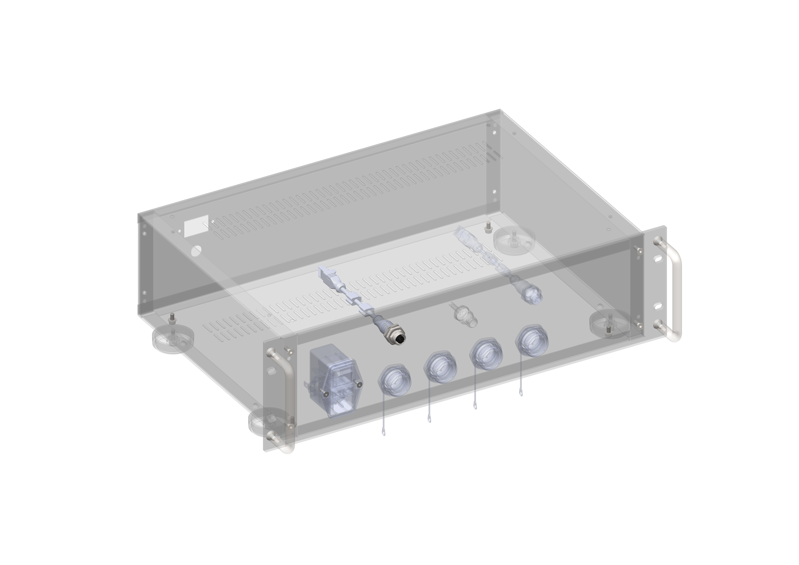
2 |
Connect the C-ETH IN on the rack. M12 connector, D-Code coding.
Mandatory connection when the machine is powered: if absent, the machine goes into ERROR (red Ready/Fault LED).
M12 → RJ45 pinout8-pole M12 → RJ45 adapter:
4-pole M12 D-code connector:
|
|
||||||||||||||||||||||||||||||||||||||||||||||||||||||||
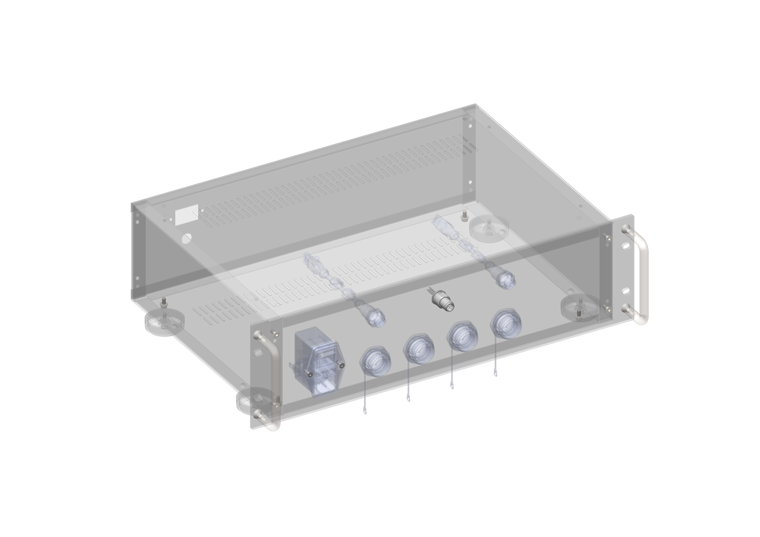
3 |
Connect the Hopper on the rack. M12 A-code connector, Modbus RTU protocol. M12 A-code pinout
|
|
||||||||||||||||||||||||||||||||||||||||||||||||||||||||
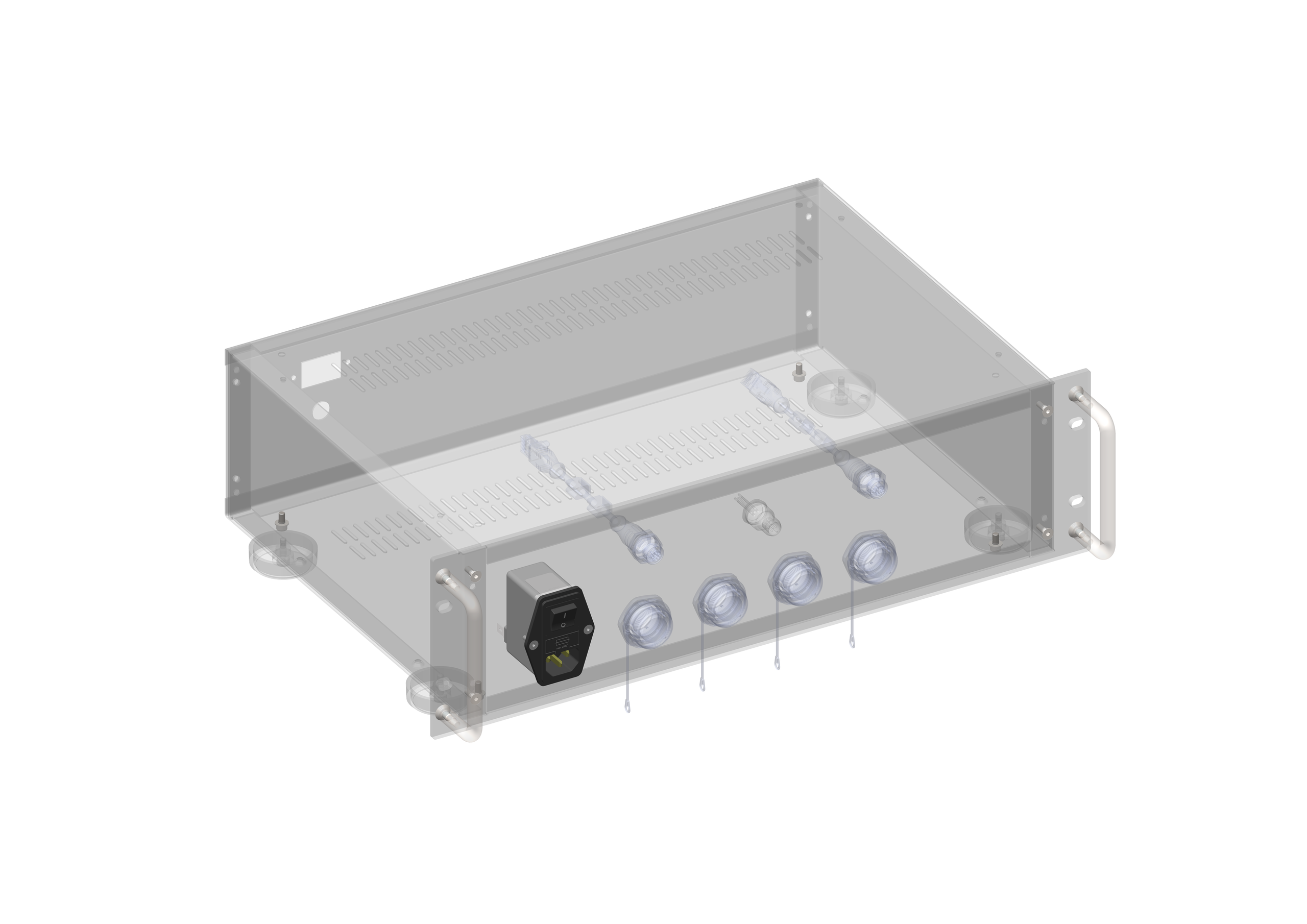
4 |
Connect the power supply on the rack — last. Power socket with switch; it also includes an IEC filter.
Make sure the FlexiBowl® is switched off before connecting the power supply.
Permitted voltage: 120–230 Vac, 50/60 Hz.
On the rack too, the power connector has a housing for the 2 protection fuses: check their condition at first start-up.
Power cable pinout diagram
|
|
Connection between Rack and FlexiBowl®#
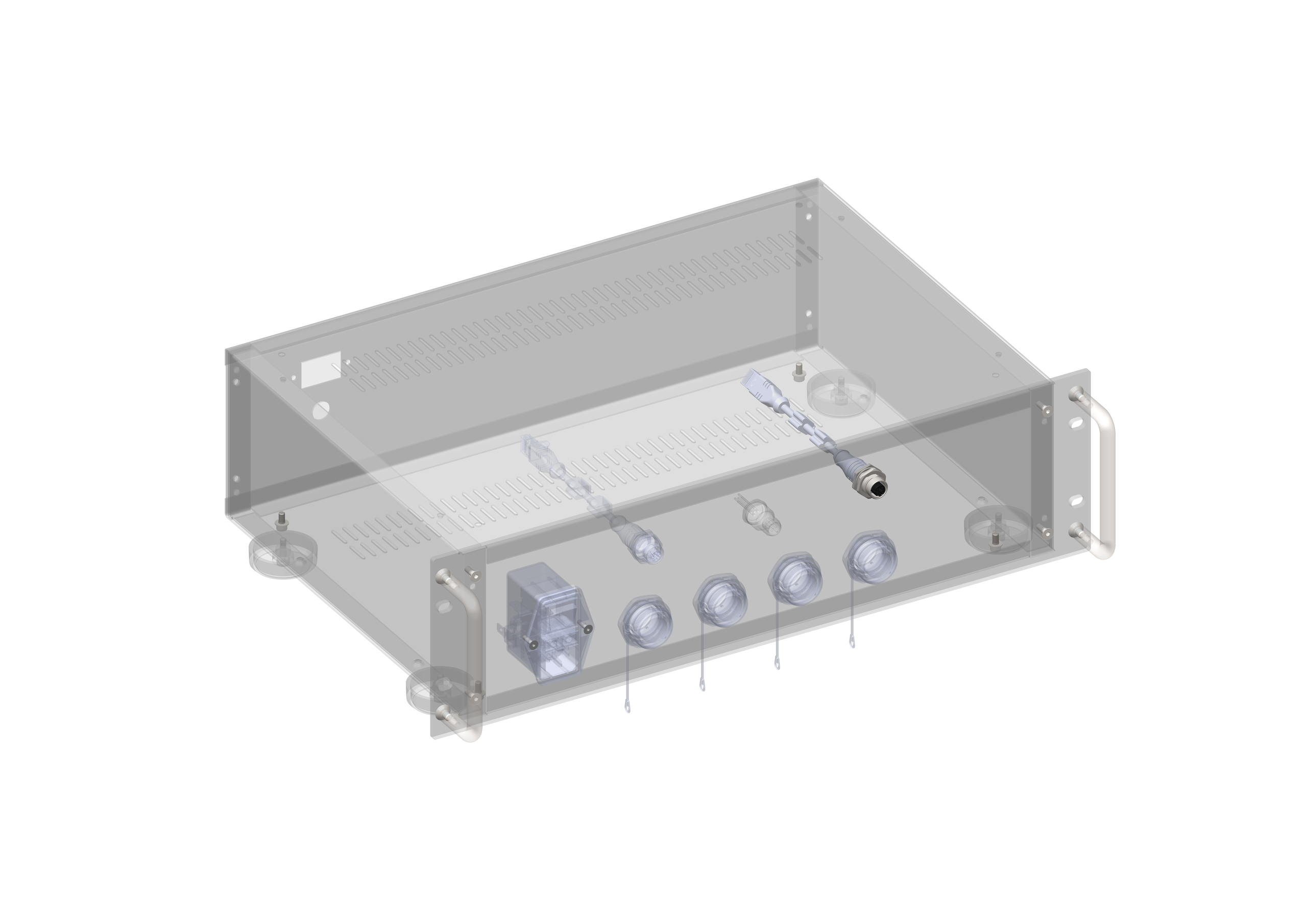
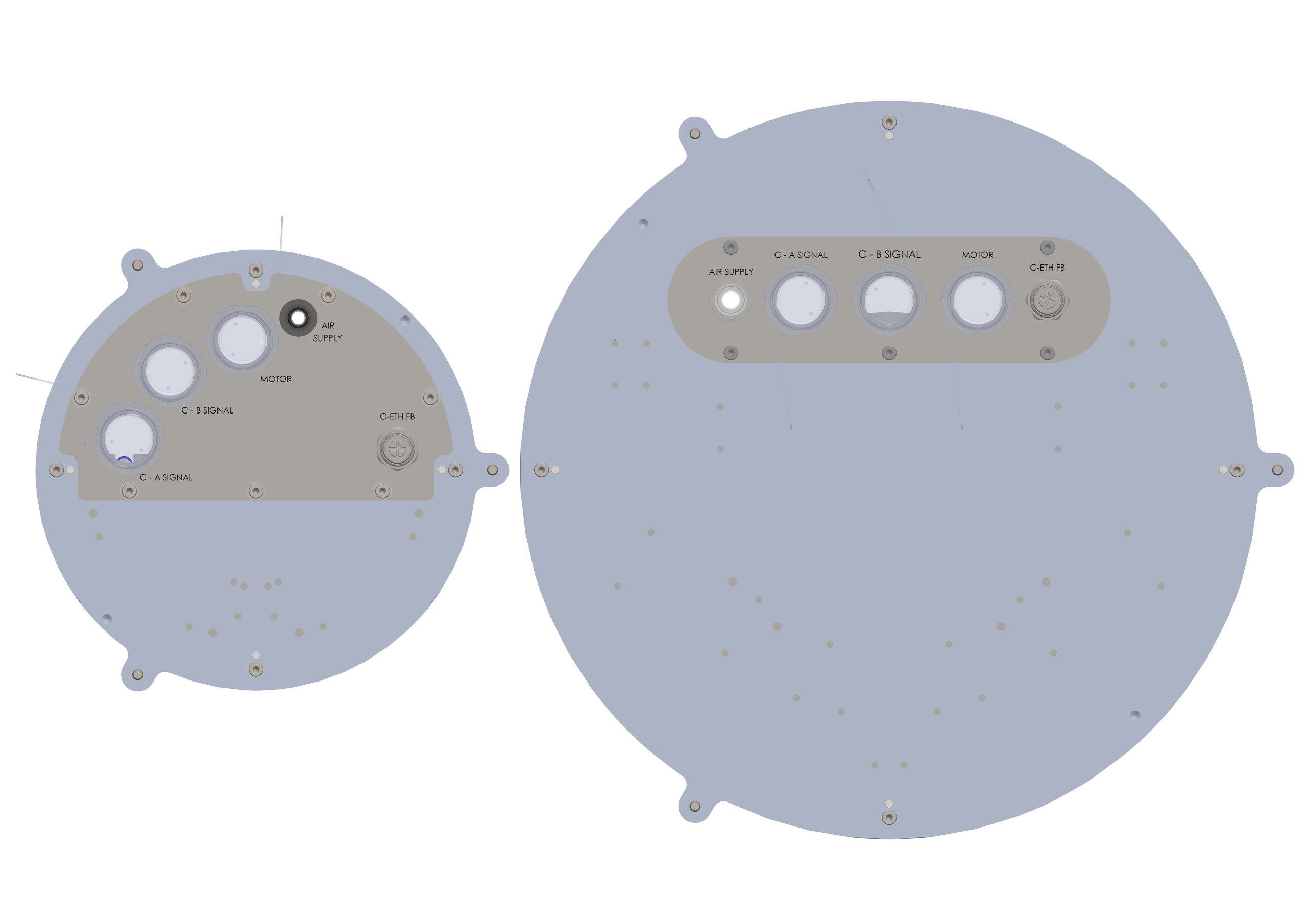
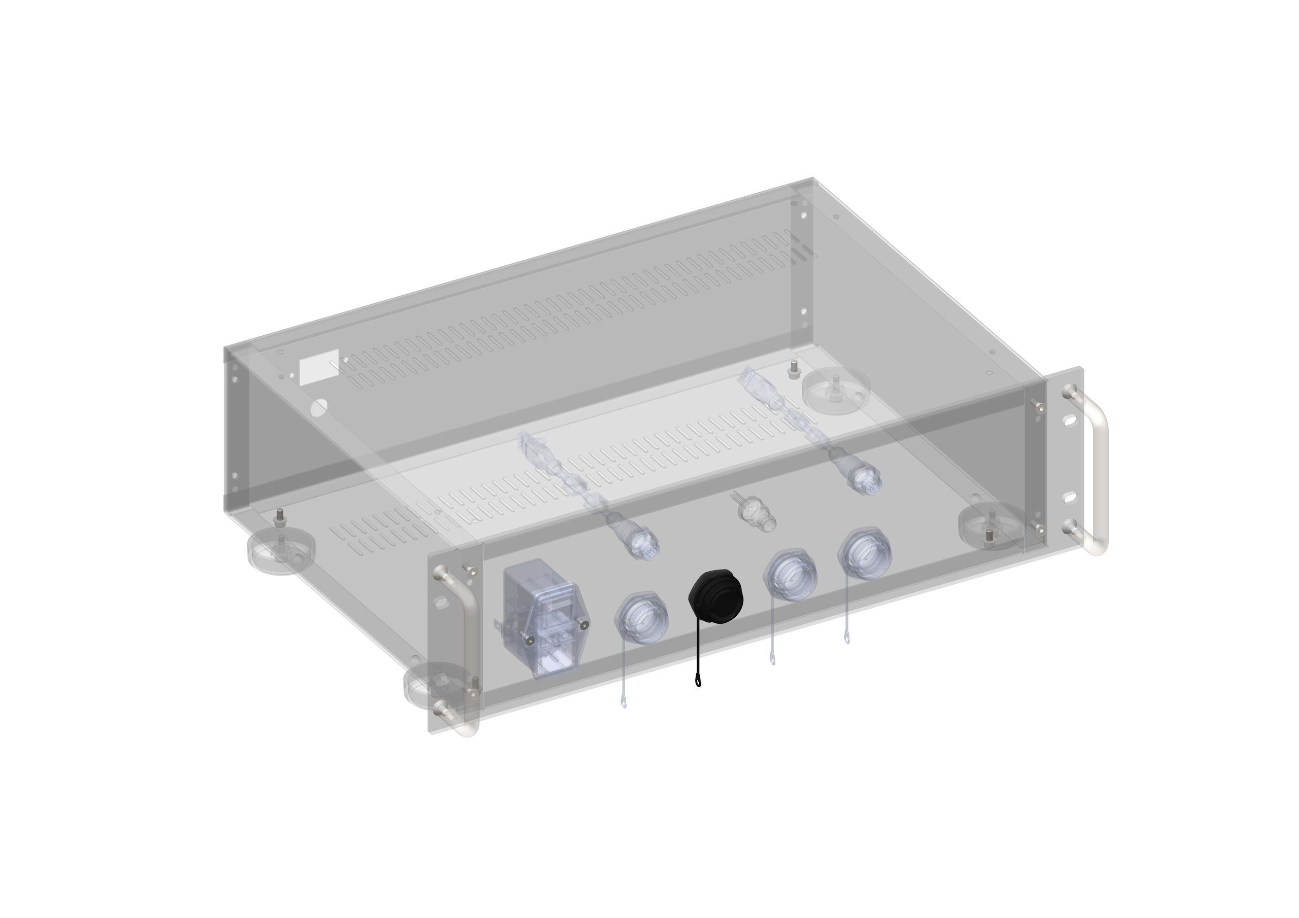
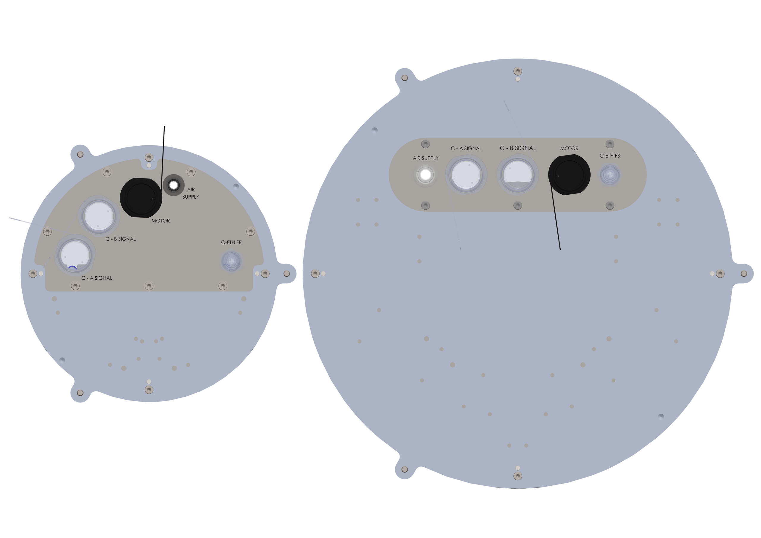
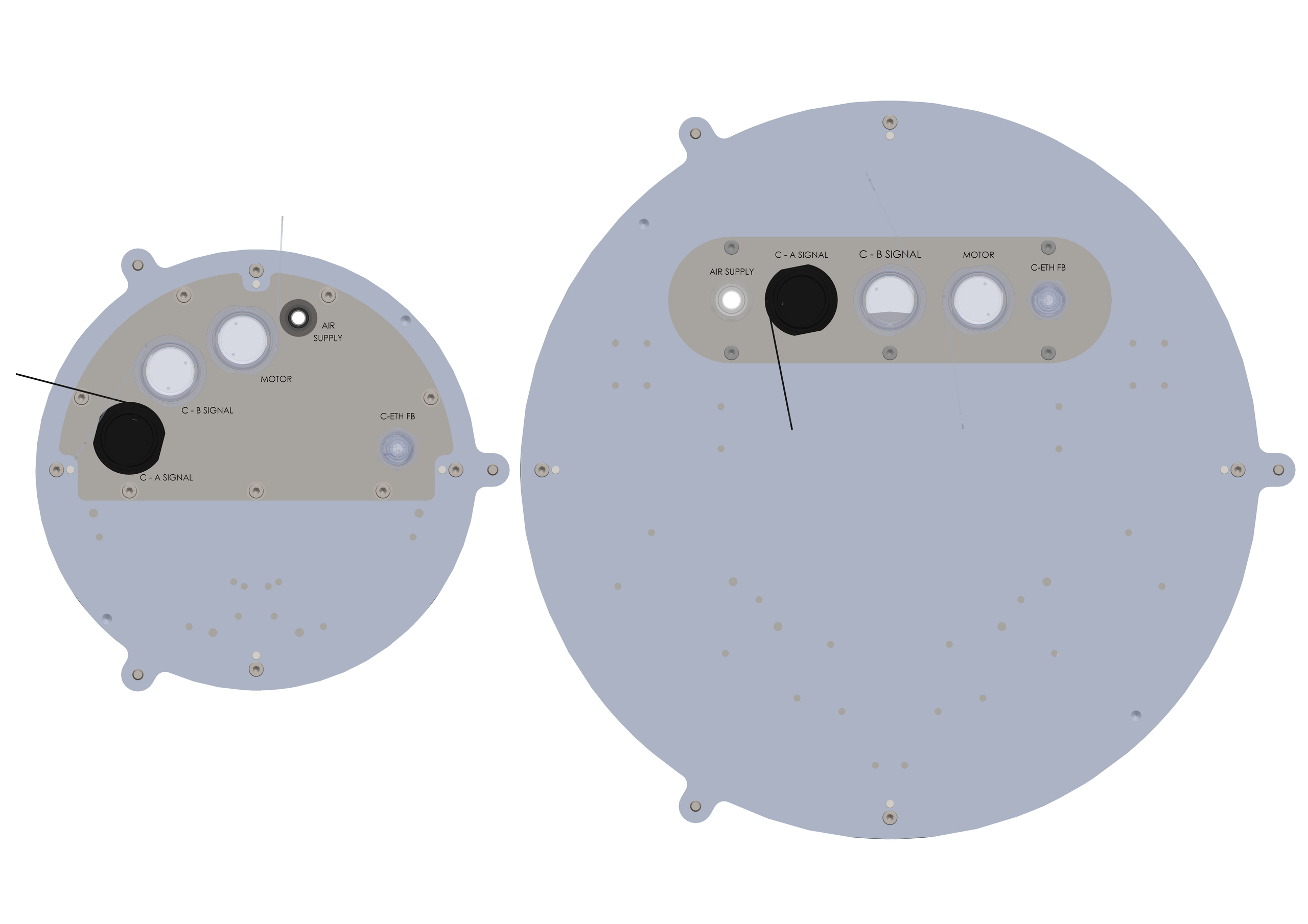
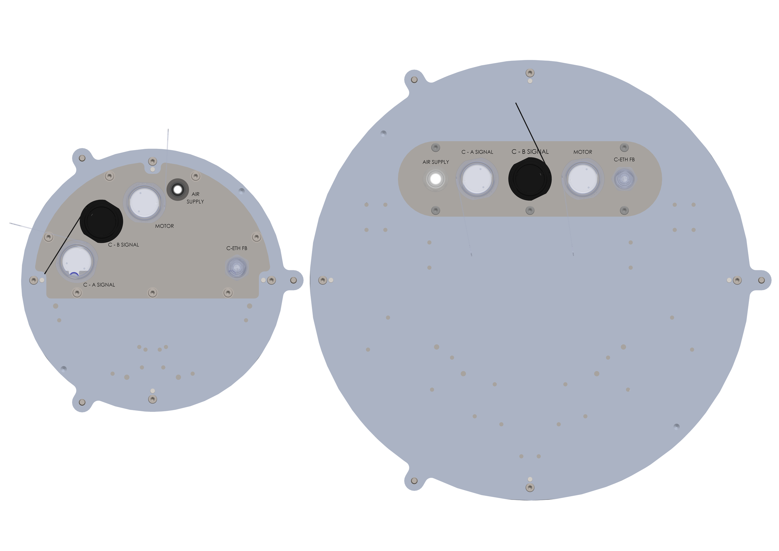
The rack communicates with the FlexiBowl® via 4 dedicated cables, each to be connected exclusively to the port with the corresponding label on the machine panel.
Attention
Connect each cable to the port with the matching label (e.g. MOTOR ↔ MOTOR, C-A SIGNAL ↔ C-A SIGNAL). A crossed connection can damage the system.
Tip
The 3 m cables between rack and FlexiBowl® are included in the supply; the 5 and 10 m versions are available as an option: see Cable for remote electronic cabinet (rack).
Action |
Image |
|||||||||||||||||||||||||||
|---|---|---|---|---|---|---|---|---|---|---|---|---|---|---|---|---|---|---|---|---|---|---|---|---|---|---|---|---|
5 |
Connect the Ethernet cable (C-ETH FB) between Rack and FlexiBowl®. M12 D-code connector. |
|
||||||||||||||||||||||||||
6 |
Connect the MOTOR cable.
9-pin connector: it carries both the motor power and the STO signals to the FlexiBowl® (on the rack, STO and Motor are separate connectors; on the cable to the machine they are combined in a single 9-pin connector).
Motor connector pinout (9 pin)
|
|
||||||||||||||||||||||||||
7 |
Connect the C-A SIGNAL cable. 12-pin connector for analog signals. C-A Signal pinout (12 pin)
|
|
||||||||||||||||||||||||||
8 |
Connect the C-B SIGNAL cable. 19-pin connector for digital signals, including the status LED activations. C-B Signal pinout (19 pin)
|
|
Note
After power-up, always check the state of the machine via the status LEDs on the front panel — see the Status LEDs section further down on this page.
Status LEDs#
On the front panel of the FlexiBowl® there are two status LEDs, common to all sizes (500–1200 and 200/350):
LED |
Color |
Meaning |
|---|---|---|
Light ON |
Green (only state) |
Indicates whether the backlight on board the FlexiBowl® is ON or OFF. The backlight is used by the vision system to illuminate the components and make them recognizable. It can be activated via the vision software or via commands from an external system communicating over Ethernet. |
Ready / Fault |
Green |
System operational and free of faults. Ethernet connection correct. |
Ready / Fault |
Red |
Internal fault or fault in the Ethernet connection. Refer to the fault table. |
Note
After power-up, wait for the Ready/Fault LED to light up: if Hopper and C-ETH are connected correctly, the LED will be green.
Circular Tracking option — Interface Panel#
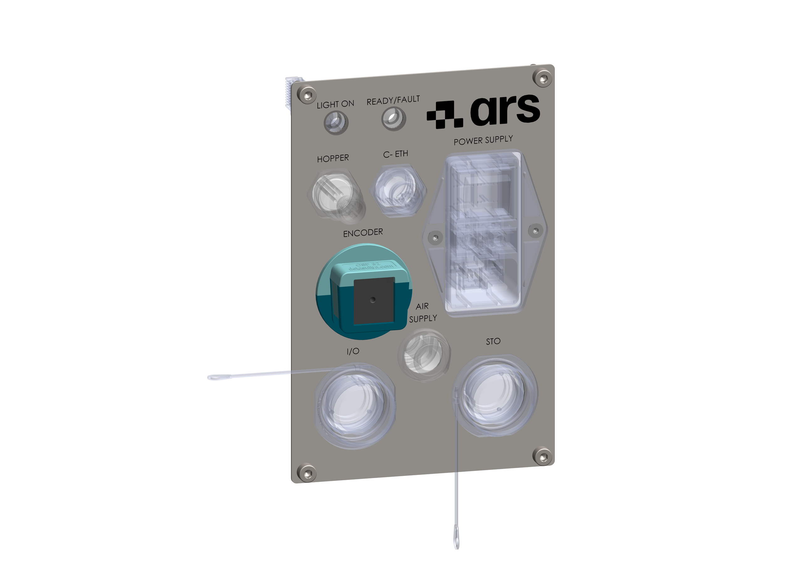
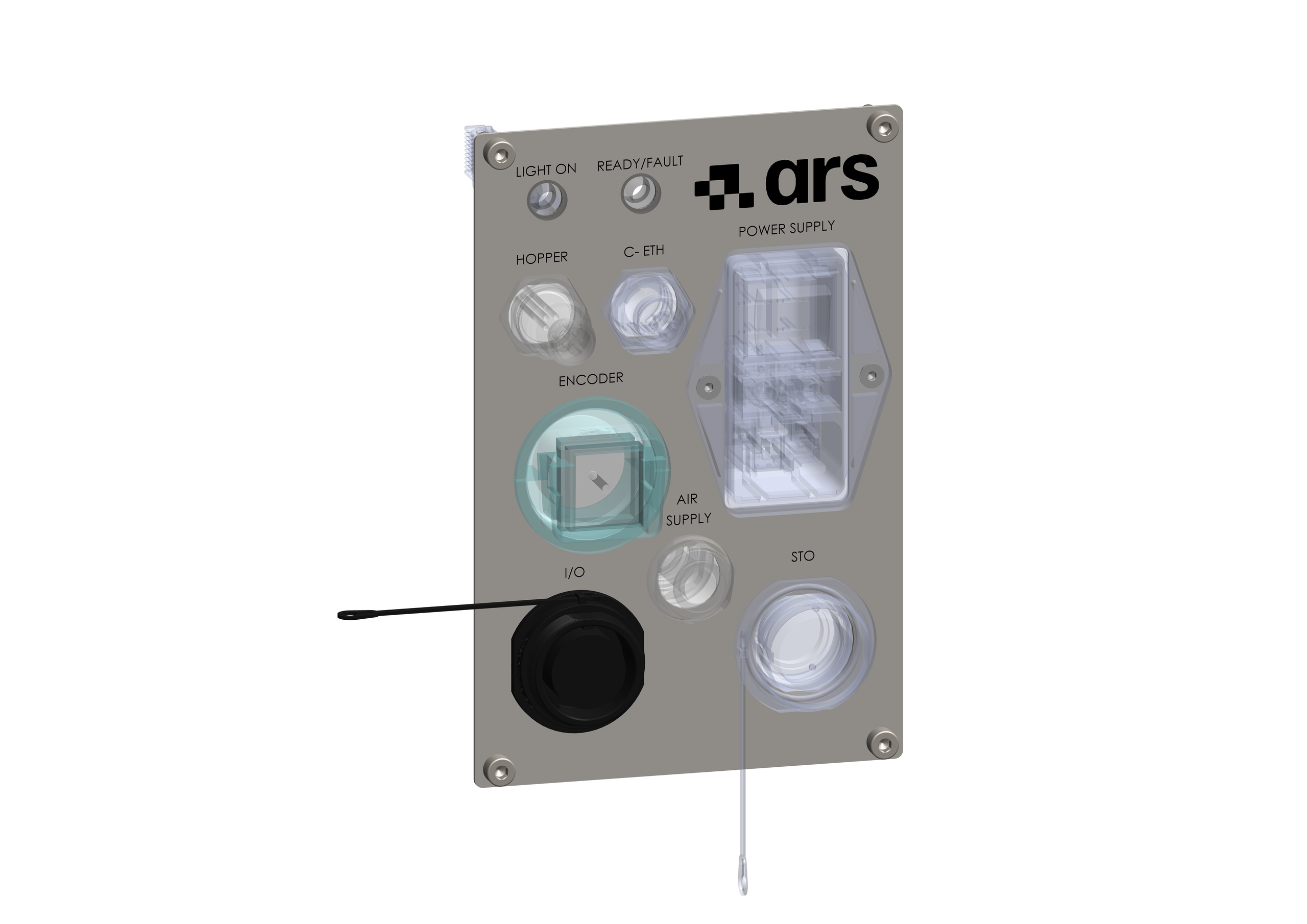
The small panel supplied with the Circular Tracking option adds, in addition to the connections already described, the following dedicated connectors:
I/O connector: exchange of digital signals, including the Latch function.
Encoder cable gland: dedicated to the encoder internal to the FlexiBowl®.
Action |
Image |
|||||||||||||||||||||||||||||||||
|---|---|---|---|---|---|---|---|---|---|---|---|---|---|---|---|---|---|---|---|---|---|---|---|---|---|---|---|---|---|---|---|---|---|---|
10 |
Connect the I/O connector (19-pin). I/O connector pinout (19 pin)
|
|
||||||||||||||||||||||||||||||||
11 |
Connect the encoder cable gland, dedicated to the encoder internal to the FlexiBowl®. |
|
General Notes and Warnings#
Attention
All connection operations must be performed with the device switched off and disconnected from the power supply.
Attention
The earth connection is mandatory and must be verified before every power-up.
Attention
In case of an anomaly indicated by the red LED (Ready/Fault), refer to the model-specific fault table.
Attention
For further technical information or assistance, contact ARS s.r.l. – FlexiBowl® Division.