

Maintenance and Troubleshooting#
Warning
Carry out maintenance operations when the machine is switched off.
Warning
Maintenance operations must be carried out by qualified and authorised personnel.
Maintenance of the machine includes the work (inspection, verification, checking, adjustment and replacement) that becomes necessary as a result of normal use.
Guidelines for correct maintenance:
The personnel in charge must be well trained and have a thorough knowledge of the accident-prevention rules. Unauthorised personnel must remain outside the work area during the operations.
Cleaning and adjustment activities are carried out solely and exclusively during maintenance, with the machine stopped, de-energised and with the electrical panel isolated.
Important
In case of doubt, it is forbidden to operate. Consult the Manufacturer for the necessary clarifications.
Attention
Repair or maintenance work not covered by this manual may be carried out only with the prior authorisation of ARS S.r.l. No liability for damage to persons or property can be attributed to ARS S.r.l. for work other than that described or carried out in ways other than those indicated.
Operational classification of maintenance#
Maintenance type |
Description |
|---|---|
Routine maintenance |
Preventive operations to ensure the proper operation of the machine over time (inspection, checking, adjustment, cleaning and lubrication). |
Extraordinary maintenance |
Corrective work as needed (overhaul, repair, restoration of nominal conditions or replacement of a faulty, defective or worn unit). |
Safety Warnings#
Attention
Before starting any maintenance work on the machine, isolate and lock out all energy sources, and put the moving units that make it up into a safe locked condition. Place the sign “Machine under maintenance - do not switch on the power” at the main switch.
Attention
When the machine is under maintenance, to prevent it from being accidentally put into operation, place signs with the wording: “WARNING! Machine Under Maintenance”.
Routine Maintenance#
Routine maintenance keeps the mechanical condition and cleanliness of the machine under control. The intervals indicated refer to normal operating conditions.
Important
For routine maintenance of machines from external suppliers, refer to the attached sub-supplier manuals.
Important
When tightening screws, always use LOCTITE 243 to ensure a perfect anti-vibration lock.
Checks and inspections#
Routine maintenance table – Checks#
Operation |
Daily |
Weekly |
Monthly |
Six-monthly |
Annual |
|---|---|---|---|---|---|
Check the condition of the tank before each start-up |
◈ |
||||
Check the state of wear of the relays |
◈ |
||||
Check the fuses for correct operation |
◈ |
||||
Check the state of wear of the leaf springs |
◈ |
||||
Check the electromagnet for correct operation |
◈ |
||||
Check the wear of the polyurethane coating (where present) |
◈ |
Checking the safety devices#
To check the integrity of the protection systems, carry out the following steps:
Cleaning#
Attention
Cleaning operations must be carried out only by qualified and authorised personnel.
Attention
To clean the machine, do not use sponge fragments, damp and/or abrasive cloths, linting rags, petrol or flammable solvents as detergent.
Attention
Do not use acids or aggressive chemical solvents to clean the base of the Bulk Feeder.
Important
Use mild, non-abrasive products, such as neutral degreasers or ordinary household soap. To remove fragments and dust, use a brush, taking care to wear protective glasses.
Routine maintenance table – Cleaning#
Operation |
Daily |
Weekly |
Monthly |
Six-monthly |
Annual |
|---|---|---|---|---|---|
Removal of process residues and waste from the tank surface |
◈ |
||||
Removal of grease and oil with neutral products or solvents |
◈ |
||||
General cleaning of the machine |
◈ |
General cleaning procedure#
Important
General cleaning of the machine must be carried out whenever the type of component to be processed is changed, so as to eliminate contaminating residues from the previous processing.
Extraordinary Maintenance#
Attention
Extraordinary maintenance and repair of the machine are reserved for qualified, trained and authorised technicians employed by the Manufacturer or by the authorised service centre.
If exceptional events occur that require extraordinary work, the user’s in-house maintenance personnel must:
Precisely check the state of the damaged or out-of-phase units.
Carry out only the operations described in this paragraph, if authorised.
If the operations are not covered in this manual, send the Manufacturer a detailed report of the facts, the result of the inspection and the observations noted.
Attention
The spare parts to be replaced must be ordered directly from ARS S.r.l. If original spare parts, or parts authorised in writing, are not used, the Manufacturer declines all liability for the operation of the machine and for the safety of the operators.
Attention
Disconnect the electrical and pneumatic power supply before carrying out any extraordinary maintenance operation or before removing the protective covers.
Important
When tightening screws, always use LOCTITE 243 thread-locker to ensure mechanical hold.
Air gap adjustment#
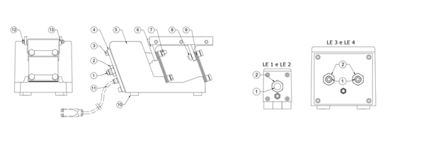
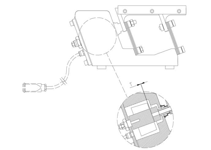
The air gap is the physical distance between the core and the counter-core; millimetre-precise adjustment is essential:
Air gap too narrow: The surfaces of the core and counter-core come into mechanical contact during operation, causing “hammering”.
Air gap too wide: The electric current of the vibrator can rise to critical levels, causing the winding to burn out and damage to the internal components of the controller.
Attention
Under no circumstances run the vibrator if either of the two conditions described above occurs.
Important
The air gap is properly calibrated at the factory; adjustments are necessary only in the event of improper handling or the application of overvoltages.
Operating data |
Intervention specifications |
|---|---|
Operator qualification |
Mechanical maintenance technician |
Tools to be used |
Open-ended spanner |
Air gap adjustment procedure#
Note
Air gap adjustment is a precision operation that may require repeated checks to obtain the ideal setting.
Air gap technical reference table#
Model |
Magnet size |
Required air gap |
Adjustment screw rotation |
|---|---|---|---|
1.5 l |
Ø21 |
1.5 mm |
360° (1 full turn) |
3 l |
Ø24 |
2 mm |
480° (1 turn + 1/3) |
5 l |
Ø28 |
3 mm |
720° (2 full turns) |
10 l |
Ø28 |
3 mm |
720° (2 full turns) |
20 l |
Ø28 |
3 mm |
720° (2 full turns) |
40 l |
32x30 |
3 mm |
720° (2 full turns) |
Replacing the leaf springs#
Operating data |
Intervention specifications |
|---|---|
Operator qualification |
Mechanical maintenance technician |
Tools to be used |
Open-ended spanner |
Changing the sizing of the leaf spring pack (number and thickness of the leaves) serves to vary and adapt the useful capacity of the vibrator.
Leaf spring replacement procedure#
Technical table of leaf springs and tightening torques#
Model |
Leaf spring size |
Leaf thickness |
Tightening torque and thread |
|---|---|---|---|
1.5 l |
40x48 mm |
1 - 1.5 - 2 mm |
7.5 N·m – M5 |
3 l |
40x48 mm |
1 - 1.5 - 2 mm |
7.5 N·m – M5 |
5 l |
70x82 mm |
1.5 - 2 mm |
30 N·m – M8 |
10 l |
70x82 mm |
1.5 - 2 mm |
30 N·m – M8 |
20 l |
70x82 mm |
1.5 - 2 mm |
30 N·m – M8 |
40 l |
80x91 mm |
1.5 - 2 - 2.5 mm |
70 N·m – M10 |
Replacing the tank#
Operating data |
Intervention specifications |
|---|---|
Operator qualification |
Mechanical maintenance technician |
Tools to be used |
Open-ended spanner |
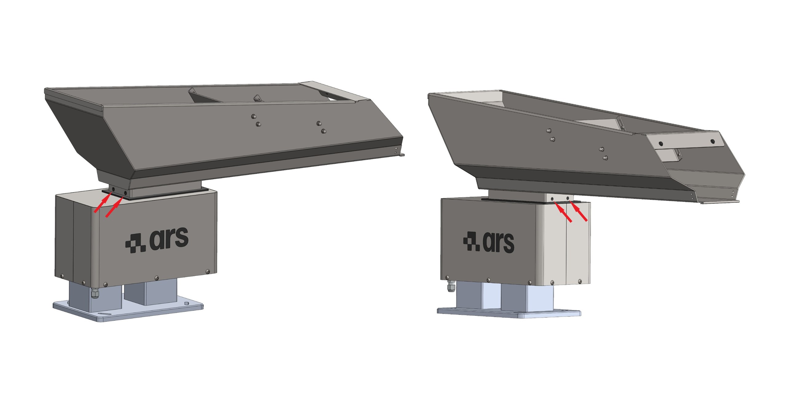
Tank removal and installation procedure#
Attention
In the case of custom models, the components may differ, partially or totally, from those indicated. For such models, refer to the project technical file.
Troubleshooting#
Attention
During normal operation the vibrator must run quietly. If a dull noise caused by internal hammering occurs, switch the system off immediately.
In the event of hammering, check and restore the optimal air gap: if the surfaces are too close they will hit each other mechanically; if too far apart, the abnormal rise in current will burn the stator windings.
Observed symptom |
Possible root cause |
Corrective action required |
|---|---|---|
The vibrator runs too slowly |
The supply voltage is below the nominal threshold. |
Increase the electrical voltage up to the correct rated value. |
The unit comes into contact with external rigid objects or adjacent structures. |
Restore the physical clearances by isolating the vibrating unit (3-5 cm). |
|
The oscillation of the leaf spring packs is obstructed or braked by accumulations. |
Disassemble, clean thoroughly and remove the residues from the leaf spring packs. |
|
The leaf springs show cracks, defects or structural yielding. |
Replace the leaf spring set immediately. |
|
The vibrating channel is cracked or mechanically worn. |
Replace the channel. |
|
The vibrator runs too fast |
The supply voltage exceeds the nominal limits (primary cause of hammering). |
Stabilise and reduce the supply voltage to the rated value. |
The unit makes noise (humming) but does not vibrate |
The electronic regulation board inside the box is faulty. |
Replace the controller’s electronic board. |
The unit does not activate and does not respond |
Total lack of electrical input power to the Controller. |
Inspect the line and remove any electrical interruptions. |
The circuit breaker or the protection fuse has tripped/blown. |
Replace the fuses or reset the breaker. |
|
The electronic board inside the control box is damaged. |
Replace the electronic board. |
|
The internal winding of the vibrator is burnt out or discharges to earth. |
Replace the electromagnet assembly. |
|
The winding has an internal short circuit. |
Replace the winding. |
|
The winding of the regulating rheostat is open. |
Replace the faulty component. |