

FlexiBowl® Installation#
Step |
Operation |
|---|---|
1 |
Place the FlexiBowl® on a stable surface. Pay attention to transport and lifting. |
2 |
Remove the handles and properly fix the FlexiBowl® to the support. The quantity and type of screws required are given in the dedicated section. |
3 |
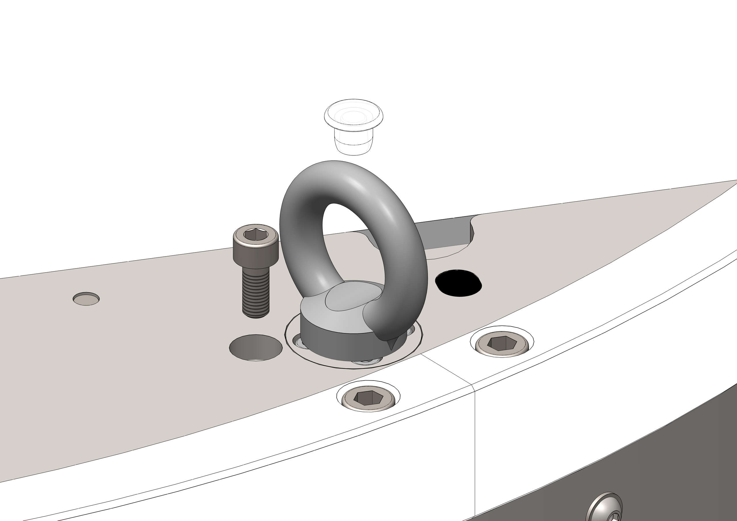
If present, remove the eyebolts:
|
4 |
|
5 |
Proceed with the necessary connections. |
Important
Leave about 100 mm of space for the FlexiBowl® power connectors.
Important
When installing the FlexiBowl® 200 and 350, pay particular attention to the rack installation specifications
Characteristics of the support surface#
Important
Make sure that the machine support surface is flat and horizontal, and suitable to bear its weight.
It is strongly discouraged to mount the FlexiBowl® on an overhanging portion of the machine table. Where this is unavoidable, make sure to stiffen the support surface sufficiently.
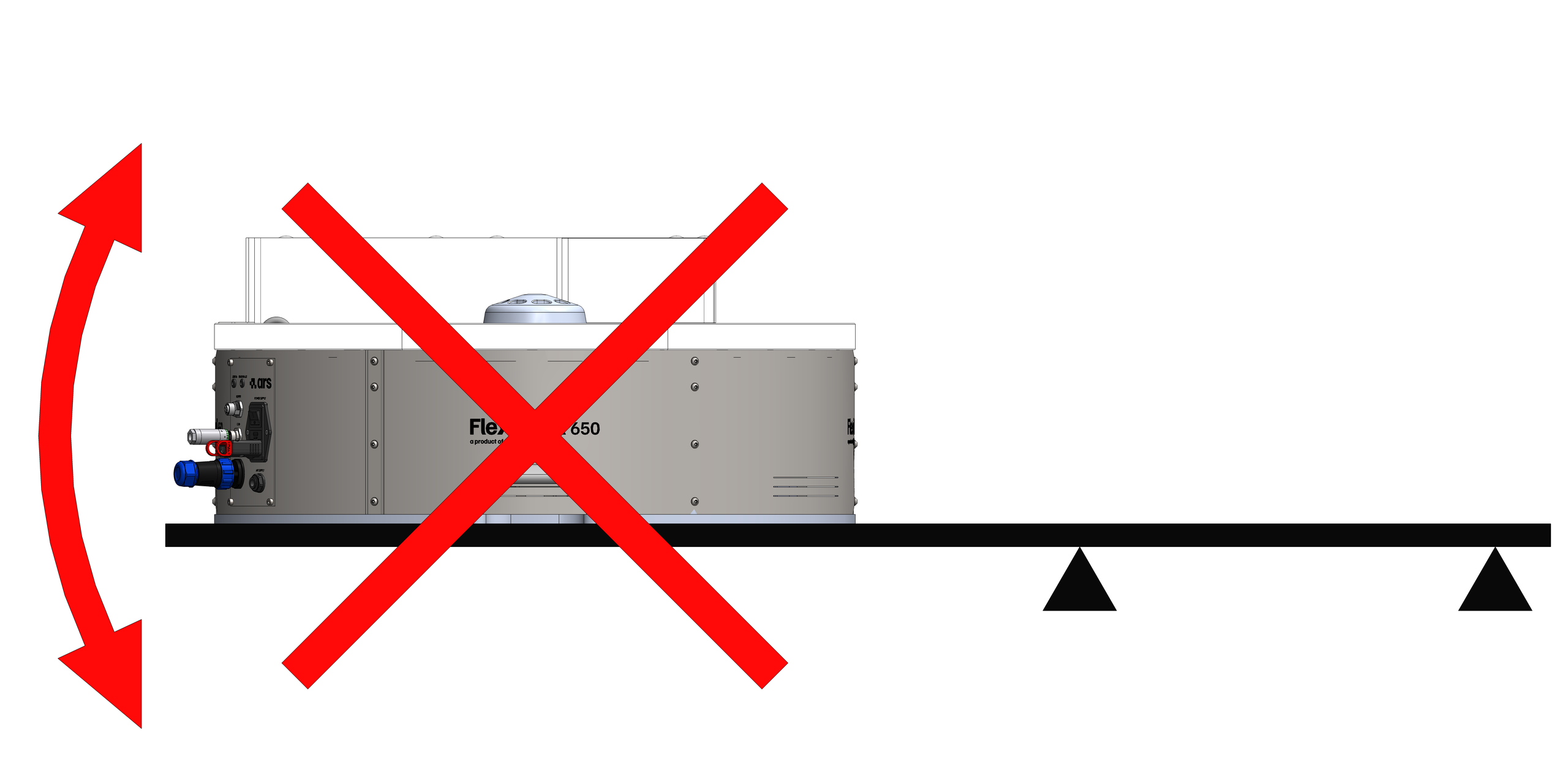
To ensure correct operation of the FlexiBowl®, the supporting surface must have flatness errors of no more than 1 mm, be mounted horizontally, and be massive enough not to be affected by the vibrations caused by the normal operation of the FlexiBowl®, the robot and any other moving parts in the layout. Indications of the minimum dimensions and weight required for mounting the FlexiBowl® are given in the table below; from these data, taking into account the material used for the base plate, the minimum required thickness can be derived.
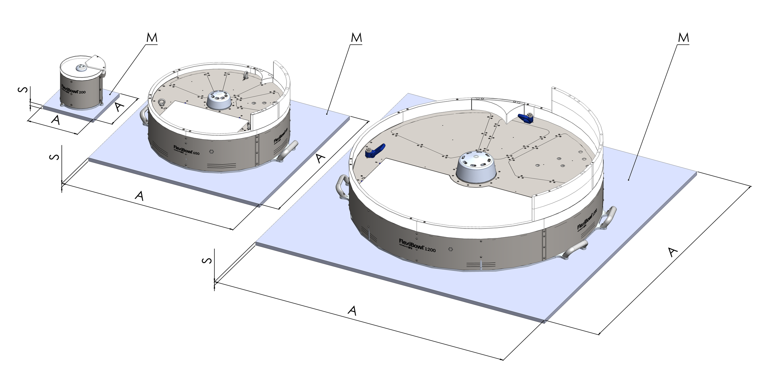
Model |
Plate dimensions AxA [mm] |
Weight M [kg] |
|---|---|---|
FlexiBowl® 200 |
≥ 276x276 |
≥ 2 |
FlexiBowl® 350 |
≥ 442x442 |
≥ 6 |
FlexiBowl® 500 |
≥ 770x770 |
≥ 16 |
FlexiBowl® 650 |
≥ 945x945 |
≥ 48 |
FlexiBowl® 800 |
≥ 1120x1120 |
≥ 68 |
FlexiBowl® 1200 |
≥ 1594x1594 |
≥ 137 |
Installing the rack box (for FlexiBowl® 200 and 350)#
To prevent the rack from overheating, it is important to leave clearance zones around it:
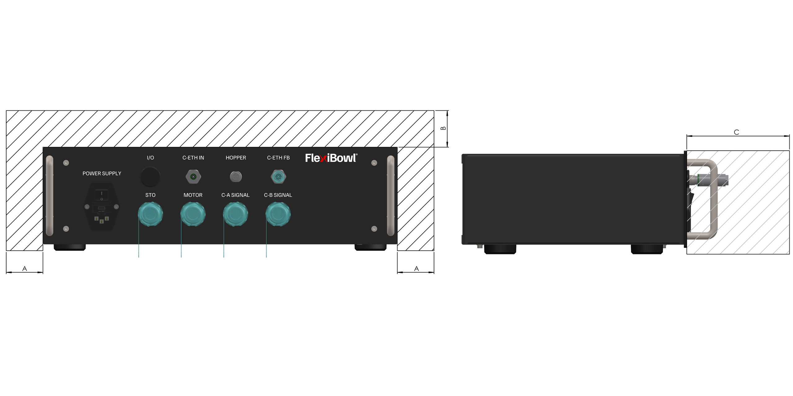
Dimension |
Value |
|---|---|
Side distance A |
10mm |
Top distance B |
50mm |
Front distance C |
100mm |
Note
The external rack for FlexiBowl® 200 and 350 is of the standard 3U type.
Note
Two racks can be installed one above the other provided that one of the following conditions is met:
the distance between the two is not less than 100 mm;
a physical barrier made of sheet metal or insulating, self-extinguishing plastic material is installed; in this case the distance between the lower rack and the wall can be reduced to 50 mm; to facilitate the extraction of hot air, the use of a barrier inclined towards the rear side of the rack can be considered.
Tip
It is useful to provide a ventilation system above the rack that forces the extraction of the hot air coming out of the upper surface, especially when several are mounted stacked vertically.