

Hopper#
Overview#
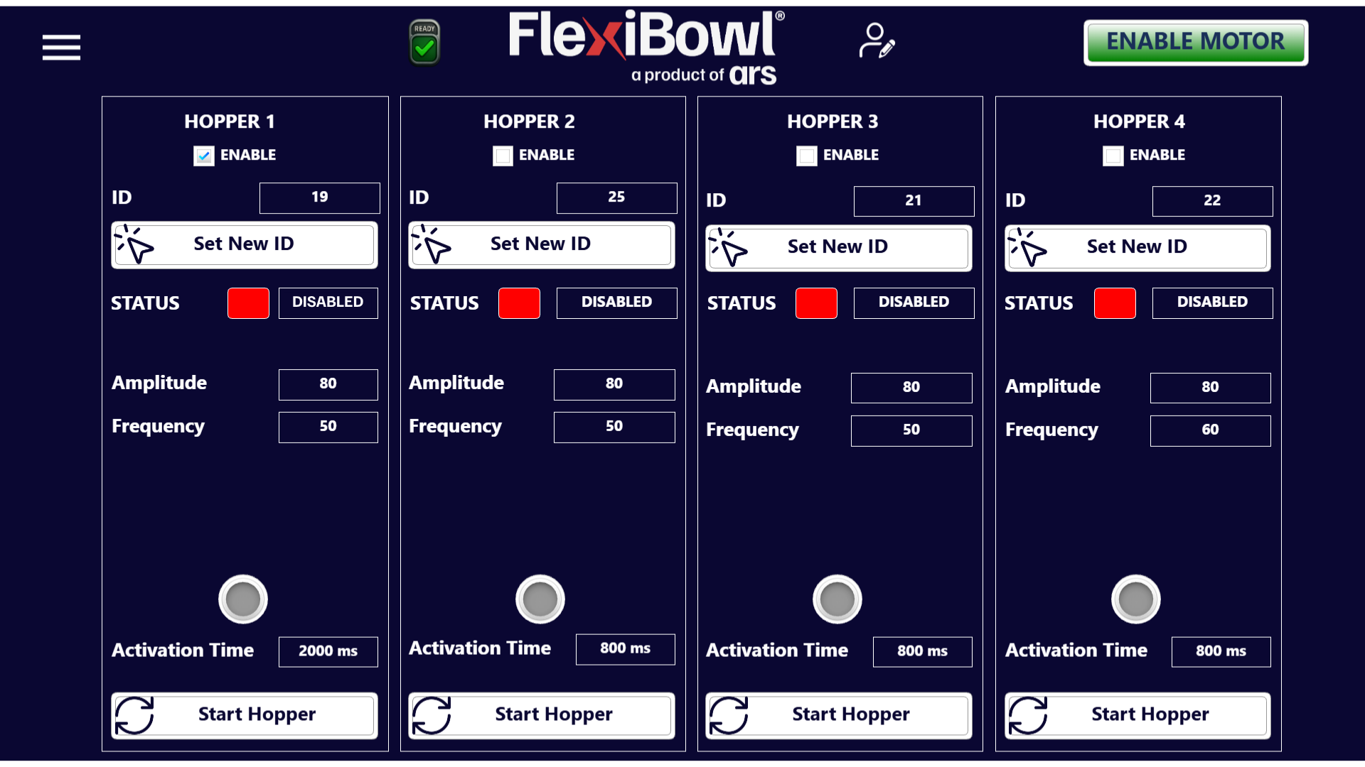
The Hopper page allows up to 4 Bulk Feeders connected to the FlexiBowl® to be configured and managed. Each hopper is a stand-alone feeding unit that supplies the FlexiBowl® with components, and can be controlled independently with its own vibration and timing parameters.
Each hopper is represented by a vertical column with the same controls, identified as HOPPER 1, HOPPER 2, HOPPER 3 and HOPPER 4.
 —
Structure of each Hopper panel#
ENABLE#
The ENABLE checkbox at the top of the panel enables or disables the corresponding hopper. Only enabled hoppers can be started and will respond to system commands.
In the example shown, only HOPPER 1 has the ENABLE checkbox selected (blue tick); hoppers 2, 3 and 4 are disabled.
Note
A disabled hopper does not respond to the Start Hopper button and is not activated during automatic sequences, even if it is physically connected to the system.
ID and Set New ID#
Field |
Description |
|---|---|
ID |
Unique identifier assigned to the hopper on the communication network |
Set New ID |
Button to assign a new ID to the hopper. Used during initial configuration or when the unit is replaced |
Warning
Change the ID of a hopper only if strictly necessary. A wrong or duplicate ID prevents communication with the hopper and can cause malfunctions in the entire feeding chain. After setting a new ID, check that it has been correctly acquired using the STATUS indicator.
STATUS#
The STATUS indicator shows the current operating state of the hopper.
LED color |
Label |
Description |
|---|---|---|
🔴 Red |
DISABLED |
The hopper is disabled |
🟢 Green |
ENABLED |
The hopper is enabled |
Vibration parameters#
Parameter |
Description |
|---|---|
Amplitude |
Amplitude of the hopper vibration, expressed in dimensionless units. Higher values produce a stronger vibration and a greater flow of components |
Frequency |
Vibration frequency of the hopper. It affects the rate at which components are conveyed toward the FlexiBowl® |
Activation Time and status LED#
Field |
Description |
|---|---|
Activation Time |
Duration of the hopper activation when it is started manually with Start Hopper or called by a sequence |
LED (grey/green) |
Indicator light that lights up while the hopper is activated |
Note
HOPPER 1 has an Activation Time of 2000 ms, while the other hoppers are set to 800 ms. Longer activation times result in a greater supply of components to the FlexiBowl® for each activation cycle.
Start Hopper#
The Start Hopper button manually starts the hopper for the duration set in Activation Time. When the time has elapsed, the hopper stops automatically.
Important
The Start Hopper button is active only if the ENABLE checkbox of the corresponding hopper is selected. Check that the hopper is enabled before attempting to start it manually.