

Machine Description#
Bulk Feeders are particularly suitable for feeding and pre-dosing small, medium and large parts. They are driven by a linear vibrating base, the model of which varies according to the size of the Bulk Feeder itself.
The standard machine consists of the following fundamental parts:
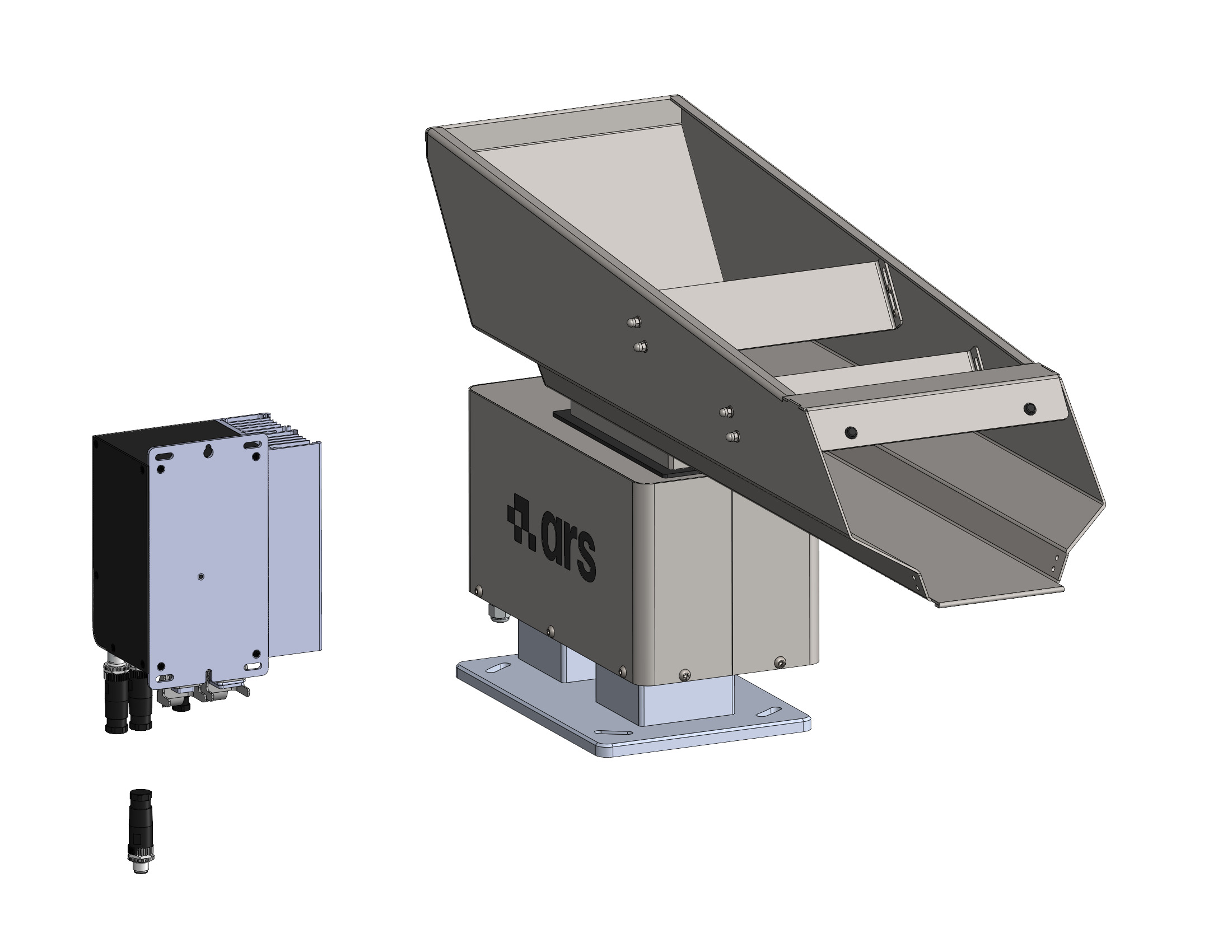
Attention
In the case of custom models, the components may differ, partially or totally, from those indicated. For such models, refer to the project technical file.
Components and Operation#
Base structure: The linear vibrating base consists of two bodies joined together by leaf springs.
Vibration mechanism: Operation relies on an electromagnet fixed to the stationary body, which attracts and releases the moving body. This action generates the vibration that makes the parts contained inside the tank advance (the tank is positioned on the moving body and locked by means of clamps).
Electrical control: To achieve this, the vibrators need a controller that converts alternating current into pulse current, as well as regulating the speed of the system itself.
Hopper and FlexiBowl® compatibility#
This page shows which feedings can be combined with each FlexiBowl® size. The must be chosen according to the FlexiBowl® size: a larger than the one indicated is not intended for smaller sizes.
Vibrating Bulk Feeders#
Hopper |
FlexiBowl® 200 |
FlexiBowl® 350 |
FlexiBowl® 500 |
FlexiBowl® 650 |
FlexiBowl® 800 |
FlexiBowl® 1200 |
|---|---|---|---|---|---|---|
Bulk Feeder PLASTIC 1.5 l |
✓ |
|||||
Bulk Feeder INOX 3 l |
✓ |
✓ |
||||
Bulk Feeder INOX 5 l |
✓ |
✓ |
||||
Bulk Feeder INOX 10 l |
✓ |
✓ |
✓ |
|||
Bulk Feeder INOX 20 l |
✓ |
✓ |
✓ |
|||
Bulk Feeder INOX 40 l |
✓ |
✓ |
✓ |
|||
Bulk Feeder Lowered Wide |
✓ |
✓ |
✓ |
Notes#
Bulk Feeder accessories (110 V version, PU coating, dosing gate, hand protection, photocells, anti-vibration kit) follow the compatibility of the tank size they refer to. See Accessories and Options.
The 1.5 l Bulk Feeder is made of plastic and does not support the accessories listed.
For FlexiBowl® accessory compatibility (lighting, diverters, air blows, discs) see Overview and compatibility.
If in doubt, or for configurations not listed, contact ARS support.
Intended Use#
The Bulk Feeder is available in six base models. Custom models, derived from the base ones but differing in size and performance, can be made after discussing the user’s requirements.
Note
Note on validity: The information contained in this manual is to be considered valid also for custom models.
Capacity of the available standard models:
Base Model |
Tank Capacity |
Load Capacity |
|---|---|---|
Model 1 |
1.5 litres |
1 kg |
Model 2 |
3 litres |
1.5 kg |
Model 3 |
5 litres |
6 kg |
Model 4 |
10 litres |
6 kg |
Model 5 |
20 litres |
6 kg |
Model 6 |
40 litres |
15 kg |
The machine in question is intended for industrial use for:
Operation |
Permitted |
Not Permitted |
Working environment |
|---|---|---|---|
Handling for the purpose of feeding:
|
Components whose maximum weight and dimensions vary according to the machine model.
|
Any other component not within the permitted maximum weight and dimension range.
|
Industrial
|
Important
For more information on the type of components permitted, see the “Technical data” paragraph of this manual.
Intended Purpose
The machine has been created to:
- meet the specific requirements stated in the sales contract;
- be used in accordance with the instructions and operating limits given in this manual.
Safety Conditions
The machine is designed and built to work safely only if:
- it is used within the limits declared in the contract and in this manual;
- the procedures in the operating manual are followed scrupulously;
- routine maintenance is carried out at the times and in the ways indicated;
- extraordinary maintenance is carried out promptly when necessary;
- the safety devices are NEVER removed and/or bypassed.
Improper Use (Reasonably Foreseeable)#
- Processing liquid components and fine grit;
- Changing working parameters in a way that compromises safety;
- Transporting people;
- Using the machine as a support point;
- Using the machine to obtain production values above the prescribed limits;
- Modifying / tampering with the electrical and pneumatic connections of the machine or any other of its components;
- Using the machine with a product other than that listed in the "Intended use (correct)";
- Using the machine in a way other than that provided for in the paragraph "Intended use (correct)".
Warning
Any use of the machine other than that intended must be authorised in writing in advance by the Manufacturer. In the absence of such written authorisation, the use is to be considered “improper use”; the Manufacturer therefore declines all liability for any damage caused to property or persons and considers any warranty on the machine to be void.
Important
Improper use of the machine excludes any liability of the Manufacturer.
Obligations and Prohibitions#
Obligations of the users#
The user (entrepreneur or employer) must:
- Take into account the capabilities and conditions of the operators in relation to their health and safety;
- Provide the personal protective equipment (PPE) suitable for the individual procedures;
- Provide lifting equipment and procedures that comply with standards;
- Require individual workers to comply with company rules and provisions on safety and on the use of the collective and individual protective equipment made available to them;
- Instruct personnel on the procedures to follow in the event of an accident;
- Instruct personnel on the residual risks present;
- Instruct personnel on the devices provided for the safety of the operators;
- Instruct personnel on the risks of noise emission in the working environment;
- Instruct personnel on the general accident-prevention rules laid down by European directives and by the legislation of the country of destination of the machine.
Note
Allow only personnel who have read this manual and have been suitably trained to operate the machine.
Obligations of the assigned personnel (operators/maintenance staff/technicians)#
Personnel must:
- Always carry out maintenance work with the machine switched off. Never lubricate moving parts;
- When the machine is running, avoid working nearby wearing chains, bracelets, ties or other clothing that could get caught in the mechanisms;
- Mandatorily tie back long hair to avoid the risk of being dragged in;
- Carry out work on the electrical panel, junction boxes, cables and electrical components only with the main switch turned off;
- Make sure that no one is inside the hazardous areas before starting the machine;
- Pay the utmost attention during operation so that no one can directly access the moving parts;
- Use appropriately the protective devices made available by the employer;
- Immediately report to the employer, manager or supervisor any deficiency or anomaly in the safety devices.
Prohibitions for operating personnel#
In particular, the personnel must not:
- Use the machine improperly (i.e. for purposes other than those indicated in the paragraph "Intended Use");
- Remove or modify the safety or signalling devices without prior authorisation;
- Carry out on their own initiative operations or manoeuvres outside their competence or that could compromise their own safety or that of other workers;
- Wear bracelets, rings or chains that could dangle and be caught by moving parts;
- Replace or change the speeds of the machine components without the explicit consent of a supervisor;
- Modify in any way the programmed cycle of the machine;
- Modify the electrical connections with the aim of excluding or bypassing the internal safety devices;
- Use the machine if it has not been installed in full compliance with the regulations in force;
- Use the machine as a support point, even if it is not running (at the risk of the operator falling and/or damage to the structure);
- Use the machine outside the permitted environmental conditions (see "Chapter 5").
Attention
ARS S.r.l. is not liable for damage caused to property or persons if: • it is ascertained that the machine has been used in one of the non-permitted environments; • the obligations and prohibitions described here have not been complied with.
Technical Data#
Bulk Feeder size |
Electrical power supply |
Frequency / Phase |
Current draw (A) |
|---|---|---|---|
1.5 l |
230Vac ±5% (115Vac on request) |
50-60 Hz / single-phase |
0.1 |
3 l |
230Vac ±5% (115Vac on request) |
50-60 Hz / single-phase |
0.1 |
5 l |
230Vac ±5% (115Vac on request) |
50-60 Hz / single-phase |
0.25 |
10 l |
230Vac ±5% (115Vac on request) |
50-60 Hz / single-phase |
0.25 |
20 l |
230Vac ±5% (115Vac on request) |
50-60 Hz / single-phase |
0.25 |
40 l |
230Vac ±5% (115Vac on request) |
50-60 Hz / single-phase |
0.45 |
Bulk Feeder size |
1.5 l |
3 l |
5 l |
10 l |
20 l |
40 l |
|---|---|---|---|---|---|---|
Corresponding net weight |
2 kg |
11 kg |
24 kg |
26 kg |
28 kg |
38 kg |
Attention
In the case of custom models, the values indicated may differ from those in the table. For such models, refer to the project technical file.
Layout#
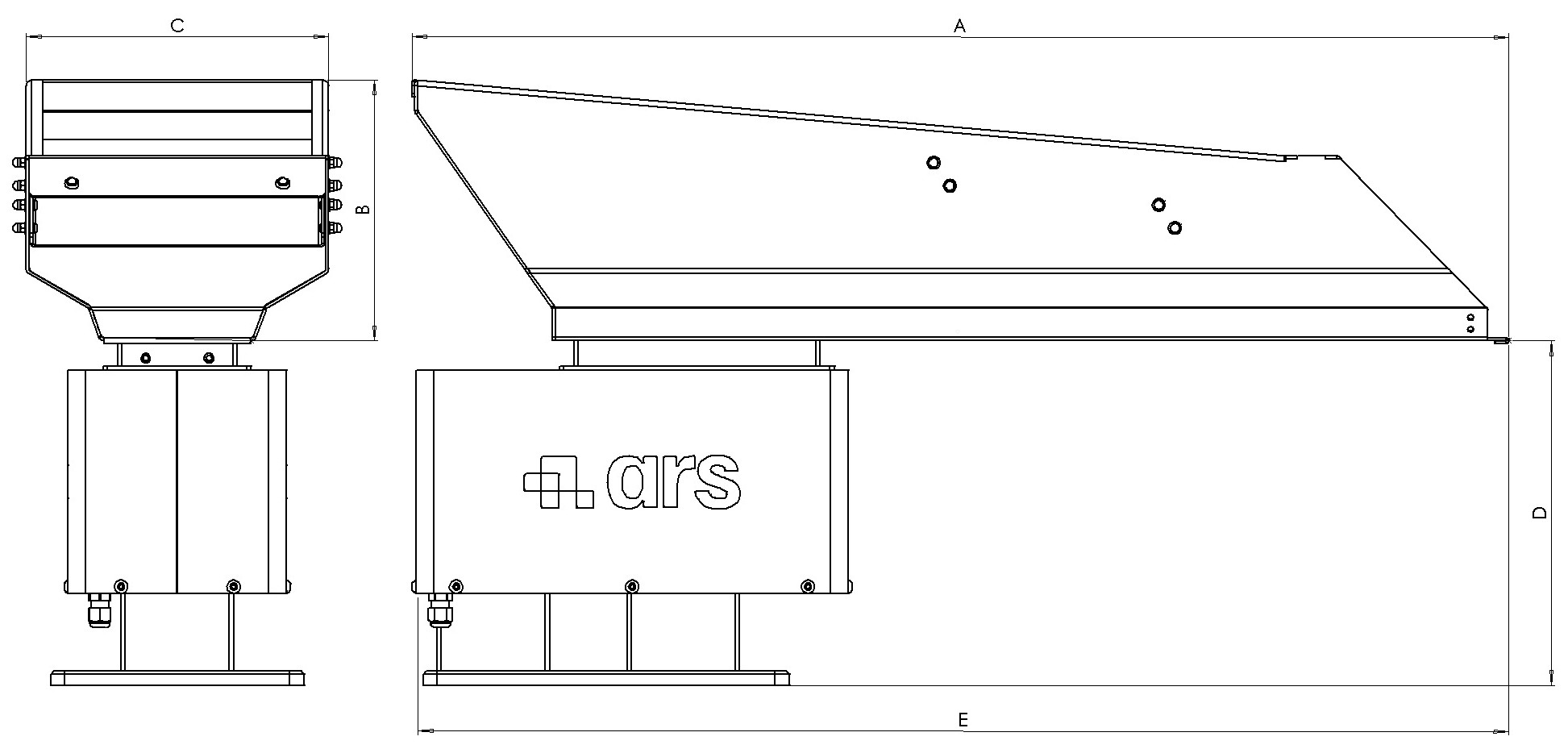
Dimensions |
1.5 l |
3 l |
5 l |
10 l |
20 l |
40 l |
|---|---|---|---|---|---|---|
A |
350 mm |
450 mm |
480 mm |
670 mm |
780 mm |
780 mm |
B |
65 mm |
100 mm |
130 mm |
155 mm |
183 mm |
208 mm |
C |
90 mm |
120 mm |
150 mm |
160 mm |
215 mm |
400 mm |
D |
211 mm |
215 mm |
233 mm |
247 mm |
247 mm |
290 mm |
E |
350 mm |
515 mm |
515 mm |
690 mm |
780 mm |
780 mm |
Attention
In the case of custom models, the values indicated may differ from those in the table. For such models, refer to the project technical file.
Standard and Optional Components#
Item |
Description |
Photo |
Standard / Optional |
|---|---|---|---|
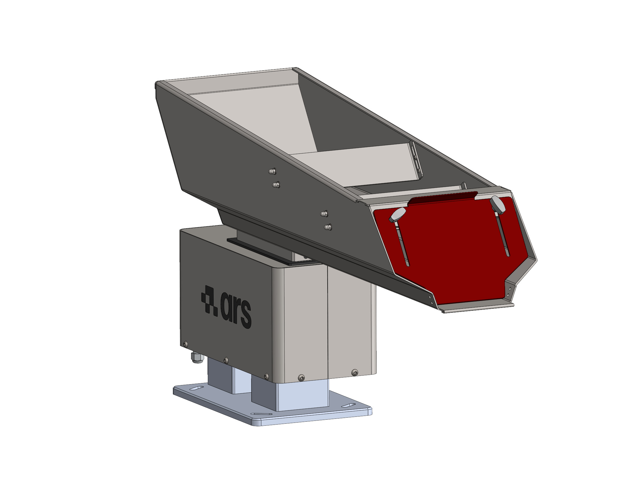
Dosing barrier |
Barrier doser for flow regulation (adjustable). See Dosing barrier. |
|
OPTIONAL (excluding 1.5 l Bulk Feeder) |
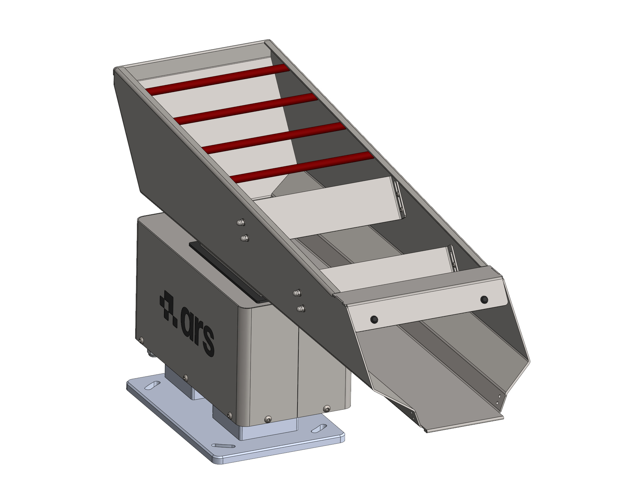
Safety guard |
Safety hand guard. See Hand guard (Hand Guard). |
|
OPTIONAL (excluding 1.5 l Bulk Feeder) |
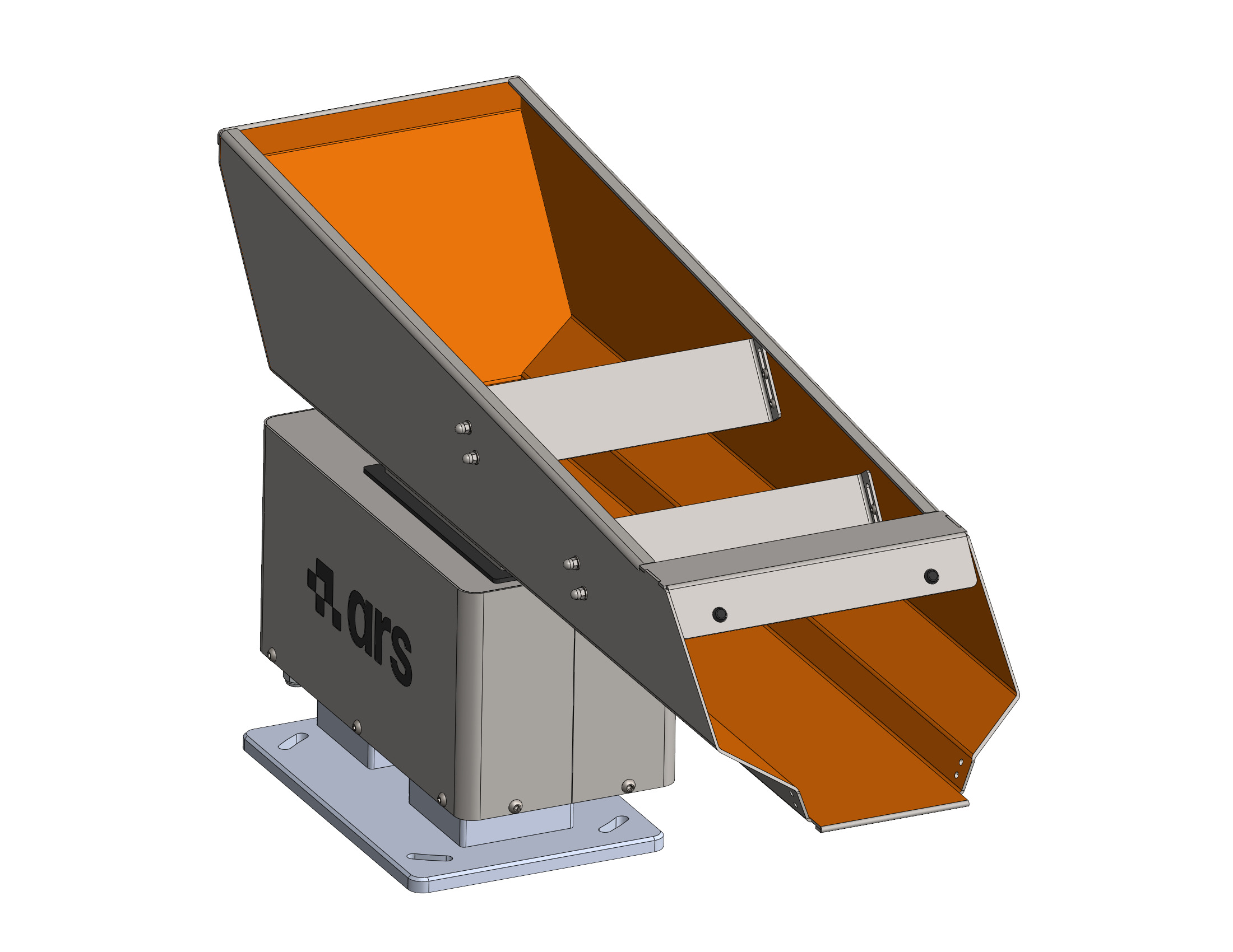
Coating |
Polyurethane coating of the tank. See Version with polyurethane (PU) coating. |
|
OPTIONAL (excluding 1.5 l Bulk Feeder) |
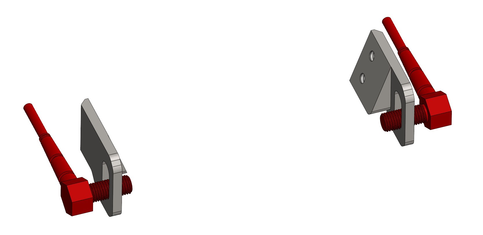
Front photocell |
Its function is to check for the presence of components in the front area of the vibrating tank during the feeding process. See Front photocell kit. |
|
OPTIONAL (excluding 1.5 l Bulk Feeder) |
Rear photocell |
Its function is to monitor the level of parts inside the tank. See Rear photocell kit. |
|
OPTIONAL (excluding 1.5 l Bulk Feeder) |
Note
The complete list of variants, accessories and options available on the price list (including the 110 V versions, the anti-vibration kits and the controller cables) is given on the Accessories and Options page.
Working cycle#
The working cycle is described below in a simplified way, divided into the following operating phases: