

Main Command#
Overview#
The Main Command page is the main operating section of the FlexiBowl® software interface. It allows the operator to configure and test the motion parameters and the accessory options of the system.
The page is divided into three subpages, selectable via the central drop-down menu located below the navigation bar, labeled “Chose Visualization Page”:
Subpage |
Brief description |
|---|---|
OPTION |
Parameters for flip, blow and backlight |
MOVE |
Parameters for the rotary movement of the FlexiBowl® |
SHAKE |
Parameters for the oscillating movement of the FlexiBowl® |
Subpage: OPTION#
The OPTION subpage collects the parameters related to the accessory functions of the FlexiBowl®: the component flipping system (flip), the blowing system (blow) and the backlighting (backlight).
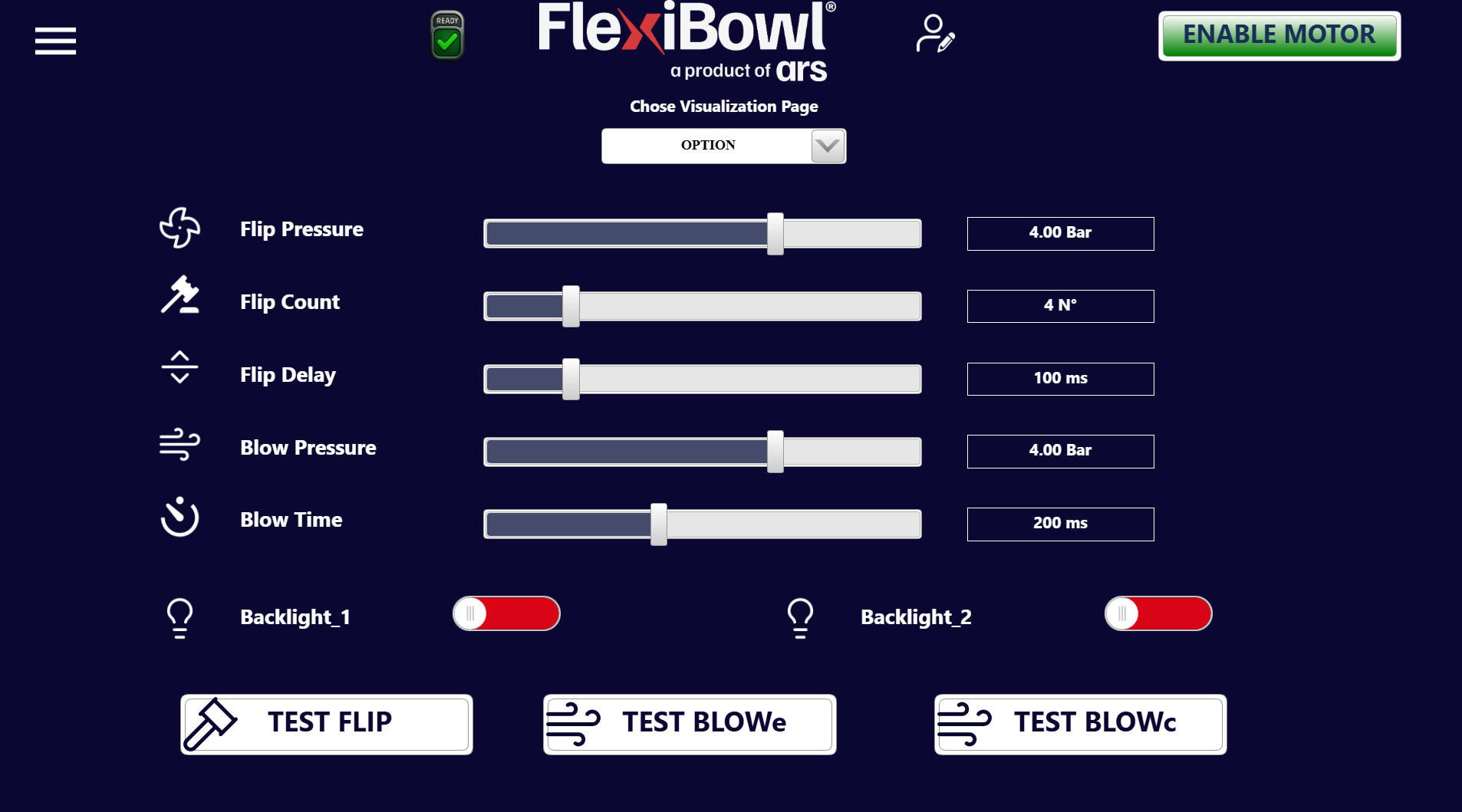
Parameter |
Unit |
Description |
|---|---|---|
Flip Pressure |
Bar |
Air pressure used for flip actuation. Adjustable via slider |
Flip Count |
No. |
Number of flips performed in sequence during a cycle |
Flip Delay |
ms |
Time interval between one flip and the next |
Blow Pressure |
Bar |
Air pressure used for blowing the components on the FlexiBowl® |
Blow Time |
ms |
Duration of the blow pulse |
Each parameter is adjustable via a horizontal slider; the current value is shown in the numeric box to the right of the slider.
Backlight controls#
Control |
Description |
|---|---|
Backlight_1 |
On/off toggle for backlight 1 |
Backlight_2 |
On/off toggle for backlight 2 |
The toggles show red when the backlight is on.
Subpage: MOVE#
The MOVE subpage allows the parameters of the rotary movement of the FlexiBowl® to be configured and tested directly from the interface.
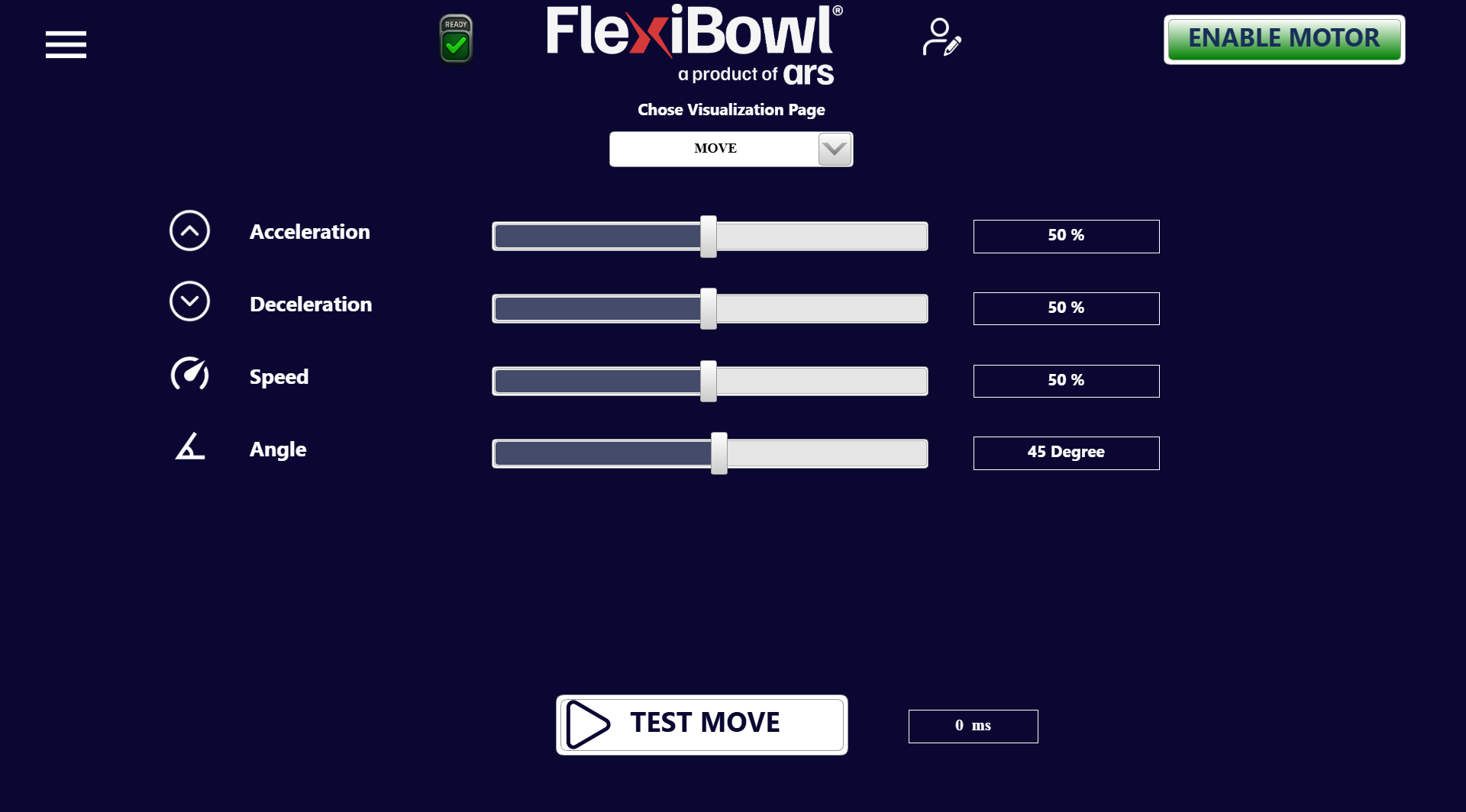
Parameter |
Unit |
Default value |
Description |
|---|---|---|---|
Acceleration |
% |
50 |
Acceleration ramp of the motor at the start of the movement. Higher values produce a more abrupt start |
Deceleration |
% |
50 |
Deceleration ramp of the motor during stopping. Higher values produce a more abrupt stop |
Speed |
% |
50 |
Rotation speed of the FlexiBowl® during the movement |
Angle |
Degree |
45 |
Rotation angle covered by the FlexiBowl® during each single movement |
Each parameter is adjustable via a horizontal slider; the current value is shown in the numeric box to the right of the slider.
Subpage: SHAKE#
The SHAKE subpage allows the parameters of the oscillating movement of the FlexiBowl® (shake), used to redistribute the components on the plate, to be configured and tested directly from the interface.
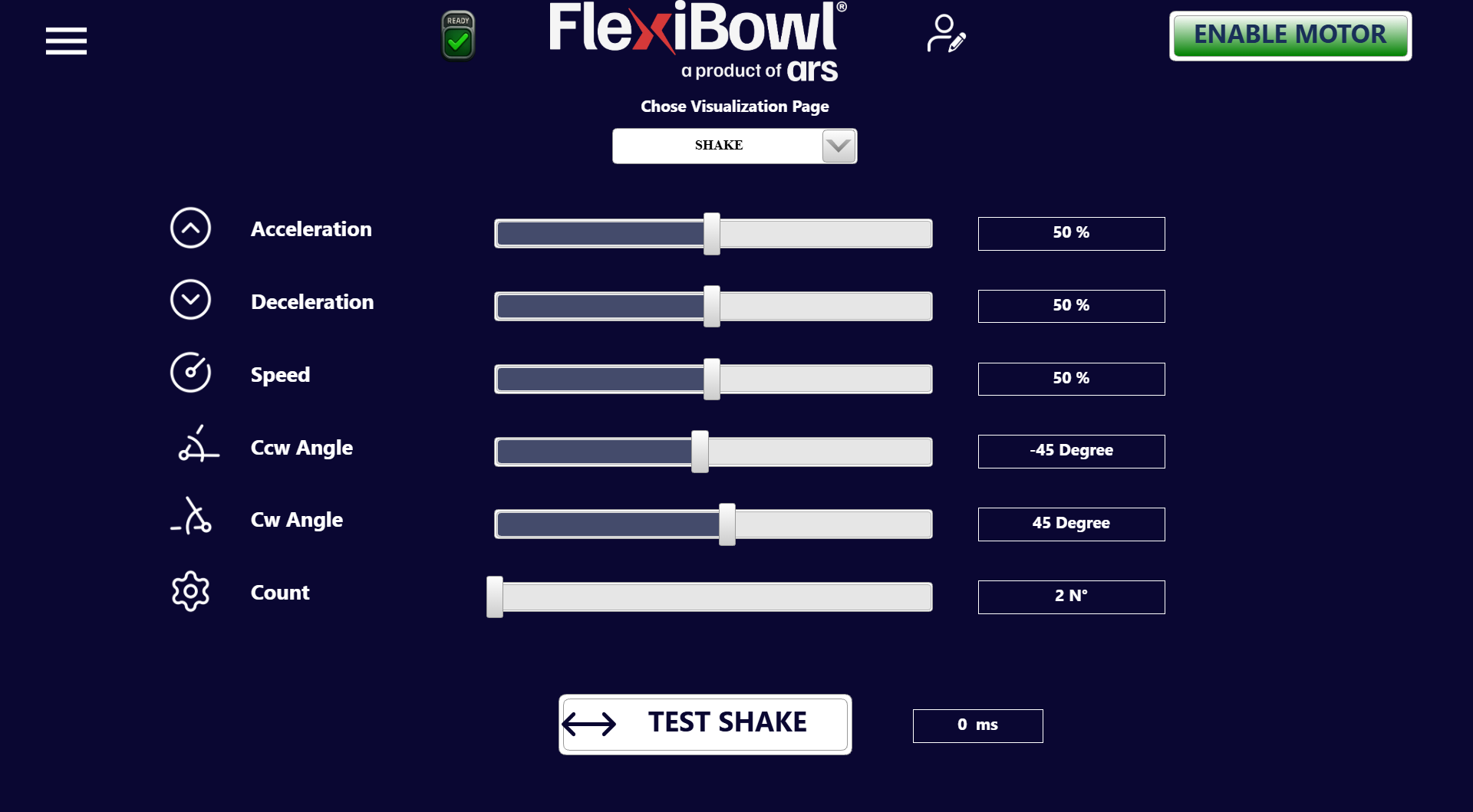
Parameter |
Unit |
Default value |
Description |
|---|---|---|---|
Acceleration |
% |
50 |
Acceleration ramp of the motor during the shake phase |
Deceleration |
% |
50 |
Deceleration ramp of the motor during the shake phase |
Speed |
% |
50 |
Rotation speed during the shake movement |
Ccw Angle |
Degree |
-45 |
Rotation angle in the counterclockwise direction (Counter-ClockWise) during each oscillation |
Cw Angle |
Degree |
45 |
Rotation angle in the clockwise direction (ClockWise) during each oscillation |
Count |
No. |
2 |
Number of complete oscillations performed during a shake cycle |
Each parameter is adjustable via a horizontal slider; the current value is shown in the numeric box to the right of the slider.
Note
The shake movement consists of a series of rotations alternating clockwise and counterclockwise, defined respectively by Cw Angle and Ccw Angle. The number of complete oscillations is controlled by the Count parameter.
Test button#
Button |
Adjacent field |
Function |
|---|---|---|
TEST SHAKE |
Execution time (ms) |
Executes a shake cycle with the currently set parameters. The field on the right shows the actual duration of the last executed shake in milliseconds |
Attention
Before running the test, make sure that the motor is enabled (ENABLE MOTOR button active) and that the system state is READY.