

Pneumatic Interface#
The machine is equipped with pneumatic actuation. Before making the pneumatic connection, verify that:
the compressed air supply system present guarantees the machine the quantity of air at the right pressure;
the compressed air tank provided is correctly sized.
The pneumatic connection must be made by connecting the main line to the machine circuit. The customer must also ensure an air supply with the characteristics listed in the “Pneumatic Technical Data” paragraph of this manual.
Warning
Never exceed 7 bar of pressure in the machine’s pneumatic system.
Warning
The FlexiBowl® is supplied without a manual shut-off and exhaust device for the pneumatic supply. The integrator must provide upstream a clearly identified, easily accessible device that can be locked in the closed position, which allows the supply to be interrupted, the residual pressure to be released and unintentional re-activation to be prevented. Pipes and fittings must be suitable for the operating pressure, correctly secured and protected against pulling out. Any further pneumatic safety devices must be defined through the risk assessment of the final machine.
Important
Mechanical maintenance technician |

|
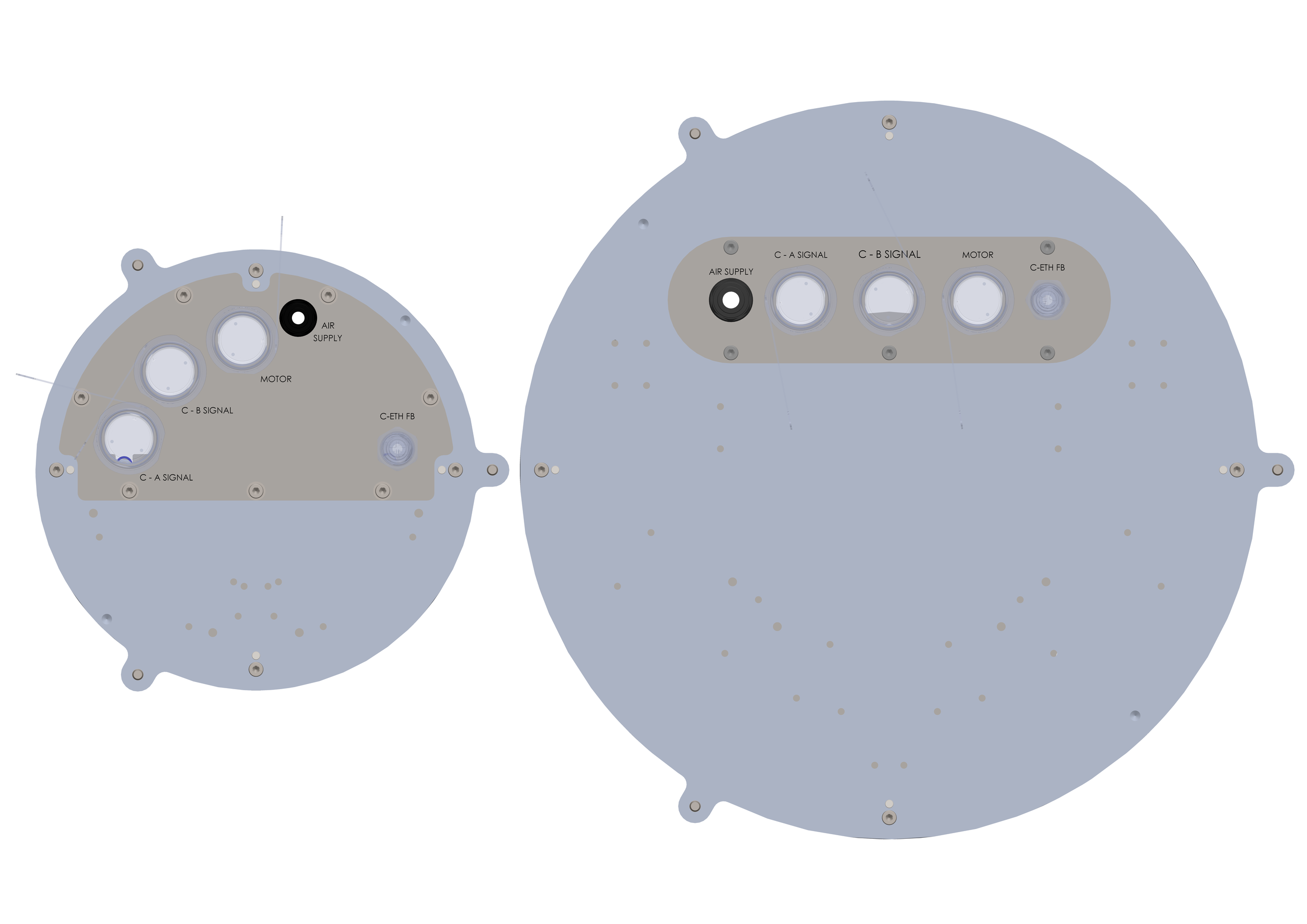
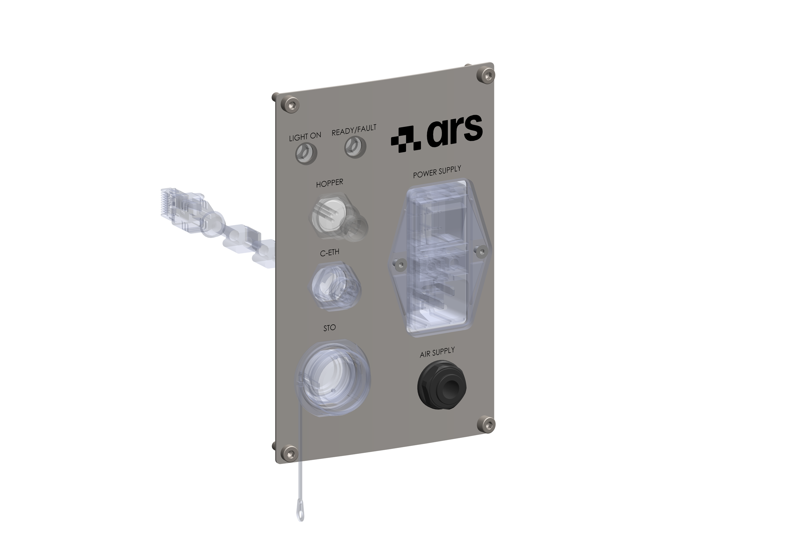
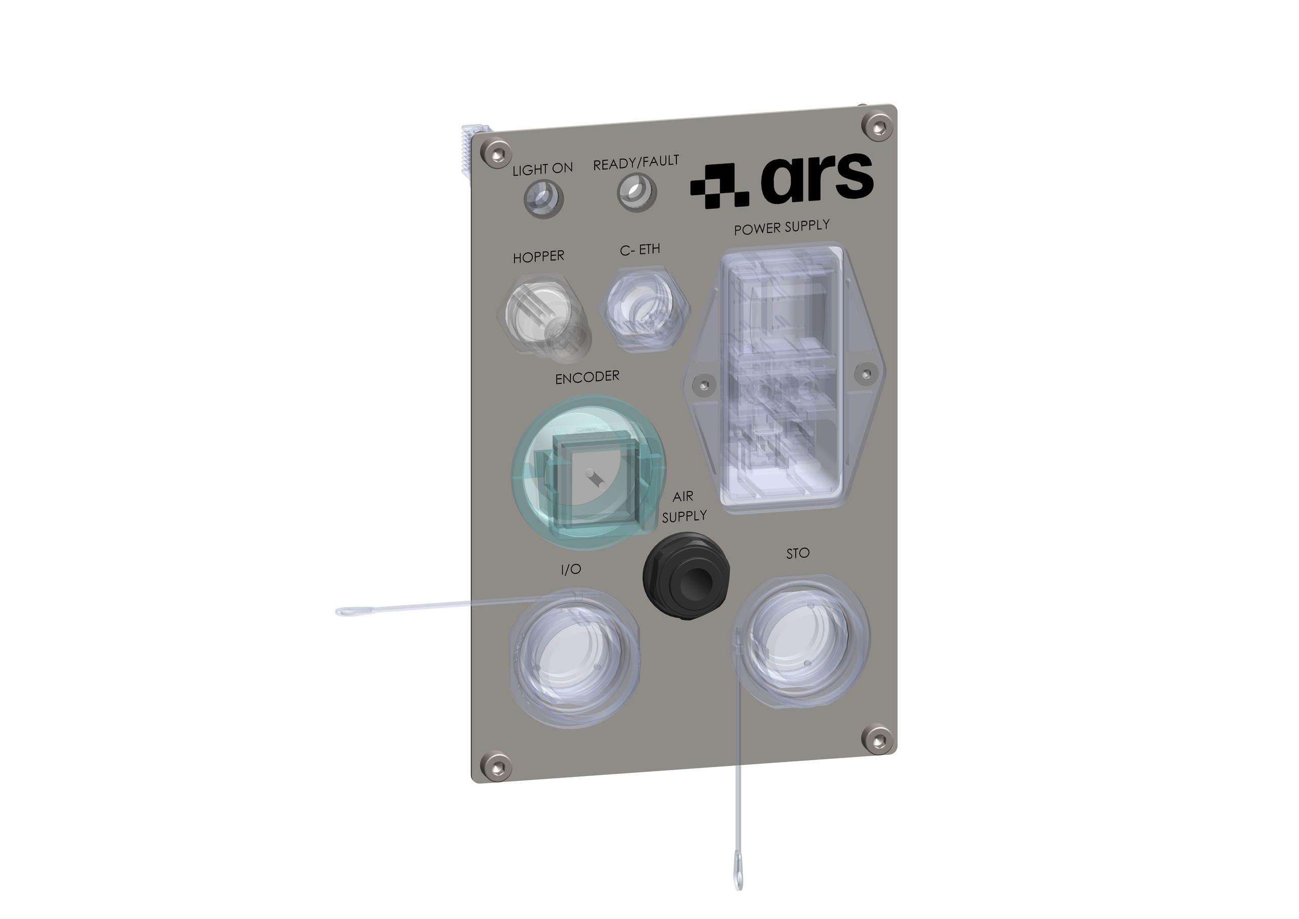
To connect to the pneumatic network, connect an air tube of the right size to the “Air Supply” inlet located on the control panel.
Required Air Characteristics#
Parameter |
Value |
|---|---|
Air quality |
Clean and dry compressed air, according to ISO 8573-1:2010, class 1.3.2 |
Recommended supply pressure |
7 bar (never to be exceeded) |
Tube diameter — FB200 / FB350 |
Ø 6 mm |
Tube diameter — FB500E / FB500 / FB650 / FB800 / FB1200 |
Ø 8 mm |
Indicative air consumption by model (Flip action)
Model |
Average consumption |
Peak consumption |
|---|---|---|
FB200 |
25 l/min |
45 l/min |
FB350 |
15 l/min |
24 l/min |
FB500E |
55 l/min |
74 l/min |
FB500 |
35 l/min |
48 l/min |
FB650 |
30 l/min |
45 l/min |
FB800 |
45 l/min |
60 l/min |
FB1200 |
135 l/min |
176 l/min |
The values shown refer to the Flip action only; for full details on consumption, refer to the “Pneumatic Technical Data” paragraph.
Note
On FlexiBowl® 3.0, pressure adjustment and gauge reading are done through the software interface, and no longer with a physical regulator and gauge on the panel as in the previous 2.0 generation.
Guided Procedure — Pneumatic Connection#
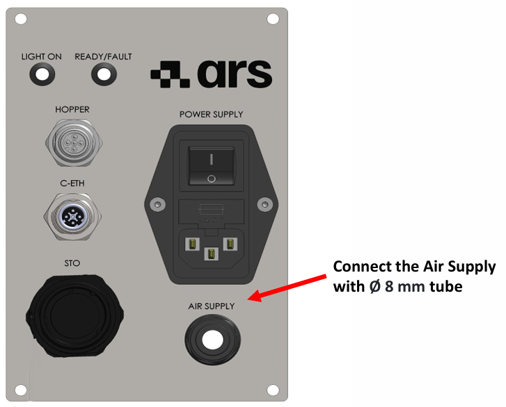
For the pneumatic connection too, the procedure changes slightly depending on the size of the machine, in particular for the tube diameter and the position of the AIR SUPPLY connector.
Attention
Before starting any pneumatic connection, make sure that the compressed air supply is disconnected and that the residual pressure in the circuit has been released.
FlexiBowl® 500 – 1200 — Standard Electrical Panel#
Action |
Image |
|
|---|---|---|
1 |
Preliminary checks. Check that the supply system guarantees the required pressure and flow rate, and that the compressed air tank is correctly sized for the installed model.
Clean and dry air according to ISO 8573-1:2010, class 1.3.2. Recommended pressure: 7 bar.
|
|
2 |
Disconnect the air supply upstream of the system, before connecting the tube.
Never connect or disconnect the air tube while the system is still pressurized.
|
|
3 |
Connect the air tube to the AIR SUPPLY inlet on the standard electrical panel, using a tube with an outer diameter of Ø 8 mm. |
|
4 |
Check the tightness of the connection: check that the fitting is correctly inserted and that there are no audible or tactile leaks along the tube and the fitting. |
|
5 |
Restore the air supply and check that the downstream pressure is within the expected parameters.
On FlexiBowl® 3.0, the pressure can be read and adjusted directly from the software interface.
|
FlexiBowl® 200 / 350#
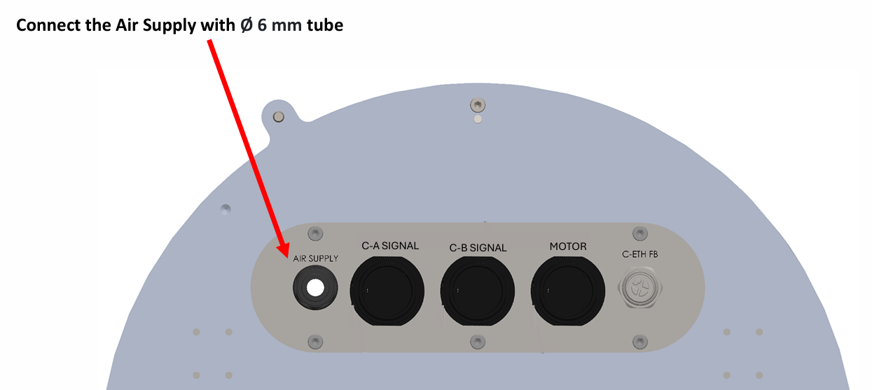
On these sizes, the AIR SUPPLY connector is located directly on the machine panel (not on the external rack), downstream of all the other wiring.
Action |
Image |
|
|---|---|---|
1 |
Preliminary checks. Check that the supply system guarantees the required pressure and flow rate, and that the compressed air tank is correctly sized for the installed model.
Clean and dry air according to ISO 8573-1:2010, class 1.3.2. Recommended pressure: 7 bar.
|
|
2 |
Disconnect the air supply upstream of the system, before connecting the tube.
Never connect or disconnect the air tube while the system is still pressurized.
|
|
3 |
Connect the air tube directly to the machine panel, using a tube with an outer diameter of Ø 6 mm. |
|
4 |
Check the tightness of the connection: check that the fitting is correctly inserted and that there are no audible or tactile leaks along the tube and the fitting. |
|
5 |
Restore the air supply and check that the downstream pressure is within the expected parameters.
On FlexiBowl® 3.0, the pressure can be read and adjusted directly from the software interface.
|
General Notes and Warnings#
Attention
All pneumatic connection and disconnection operations must be carried out with the system disconnected and residual pressure released.
Attention
Never exceed 7 bar of pressure in the machine’s pneumatic system.
Attention
The FlexiBowl® is not equipped with a manual shut-off and exhaust device: it is the integrator’s responsibility to provide one upstream, clearly identified, accessible and lockable in the closed position.
Attention
Use only tubes and fittings suitable for the operating pressure, correctly secured and protected against pulling out.
Attention
For further technical information or assistance, contact ARS s.r.l. – FlexiBowl® Division.