

FlexiBowl® Wiring#
Important
Electrical maintenance technician |

|
Warning
Before making any electrical connection, make sure that the power supply is disconnected and that the system is in a safe state.
The wiring of the FlexiBowl® varies according to the machine size:
FlexiBowl® 500 – 1200: all connections (STO, Ethernet, Hopper, power supply, air) are located on a single standard electrical panel, mounted directly on the machine.
FlexiBowl® 200 / 350: the main connections are located on an external rack; the rack is then connected to the machine via 4 dedicated cables (Ethernet, Motor+STO, signal A, signal B). Only the compressed air remains to be connected on the machine.
FlexiBowl® 500 – 1200 — Standard Electrical Panel#
Action |
Image |
|||||||||||||||||||||||||||||||||||||||||||||||||||||||||
|---|---|---|---|---|---|---|---|---|---|---|---|---|---|---|---|---|---|---|---|---|---|---|---|---|---|---|---|---|---|---|---|---|---|---|---|---|---|---|---|---|---|---|---|---|---|---|---|---|---|---|---|---|---|---|---|---|---|---|
1 |
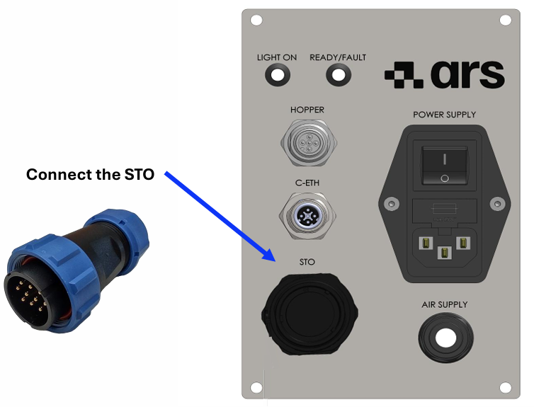
Connect the STO.
10-pin connector. The +STO1 and +STO2 inputs must receive +24 Vdc from the safety circuit; −STO1 and −STO2 must be connected to the −24 Vdc reference.
10-pin connector pinout
|
|
||||||||||||||||||||||||||||||||||||||||||||||||||||||||
2 |
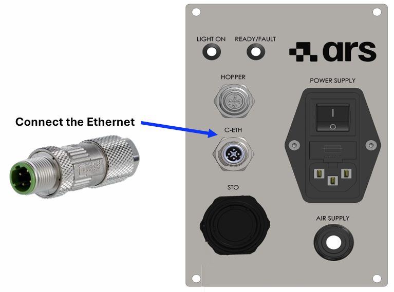
Connect the Ethernet (C-ETH).
When the FlexiBowl® is powered, the Ethernet connection is mandatory: if absent, the machine enters the ERROR state (red Ready/Fault LED).
M12 → RJ45 pinout8-pole M12 → RJ45 adapter:
4-pole M12 D-code connector:
|
|
||||||||||||||||||||||||||||||||||||||||||||||||||||||||
3 |
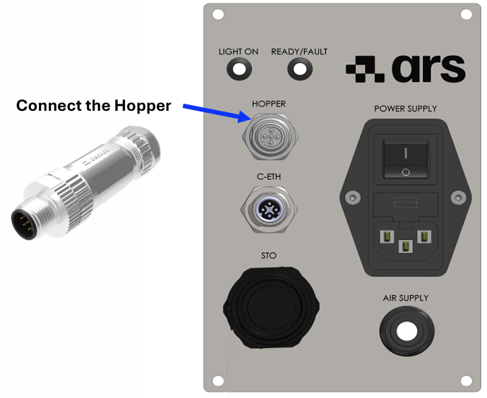
Connect the Hopper.
M12 A-code connector, used to communicate with ARS hopper controllers via the Modbus RTU protocol.
M12 A-code pinout
|
|
||||||||||||||||||||||||||||||||||||||||||||||||||||||||
4 |
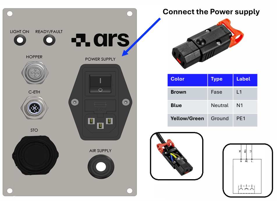
Connect the power supply (Power Supply).
Make sure the FlexiBowl® is switched off before connecting the power supply.
Permitted voltage: 120–230 Vac, 50/60 Hz.
On first start-up, check the status of the fuses. After power-on, wait for the status LED (Ready/Fault) to light up: if the Hopper and C-ETH are connected correctly, the LED will be green.
Power cable pinout diagram
|
|
||||||||||||||||||||||||||||||||||||||||||||||||||||||||
5 |
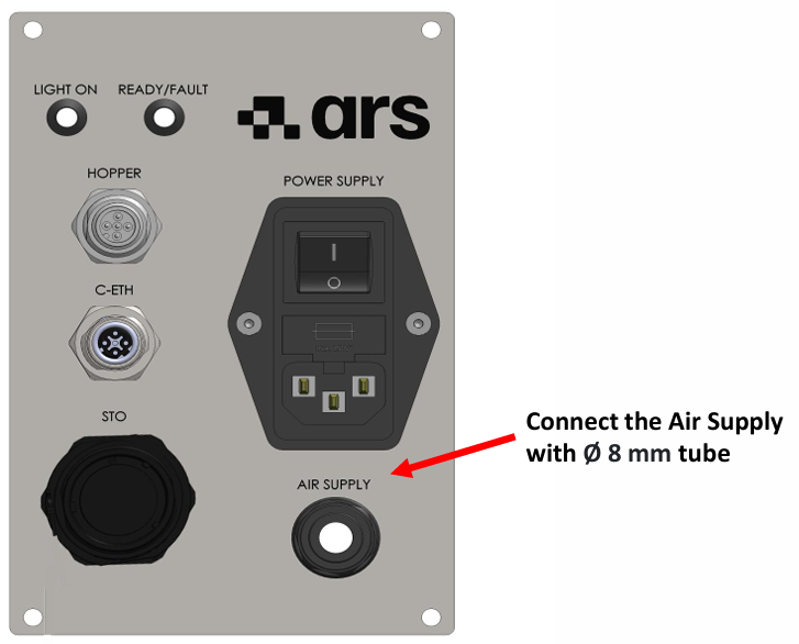
Connect the compressed air with an Ø 8 mm tube. Note For the required air characteristics (pressure, ISO cleanliness class) refer to the Pneumatic Technical Data. |
|
FlexiBowl® 200 / 350 — External Rack#
For these sizes, the connections to the customer’s facilities are located on the external rack (not on the machine). The rack must then be connected to the machine via 4 dedicated cables.
Connections on the rack#
The rack connectors are the same as those of the standard panel (same pinout), simply positioned on an external box instead of on the machine.
Action |
|
|---|---|
1 |
Connect the STO on the rack — same 10-pin connector as the standard panel (see the pinout table above). |
2 |
Connect the C-ETH IN on the rack — same M12 D-code connector as the standard panel. The same rule applies: the connection is mandatory, otherwise the machine goes into ERROR. |
3 |
Connect the Hopper on the rack — same M12 A-code connector (Modbus RTU) as the standard panel. |
4 |
Connect the power supply on the rack — 120–230 Vac.
Make sure the FlexiBowl® is switched off before connecting the power supply.
|
Connection between Rack and FlexiBowl®#
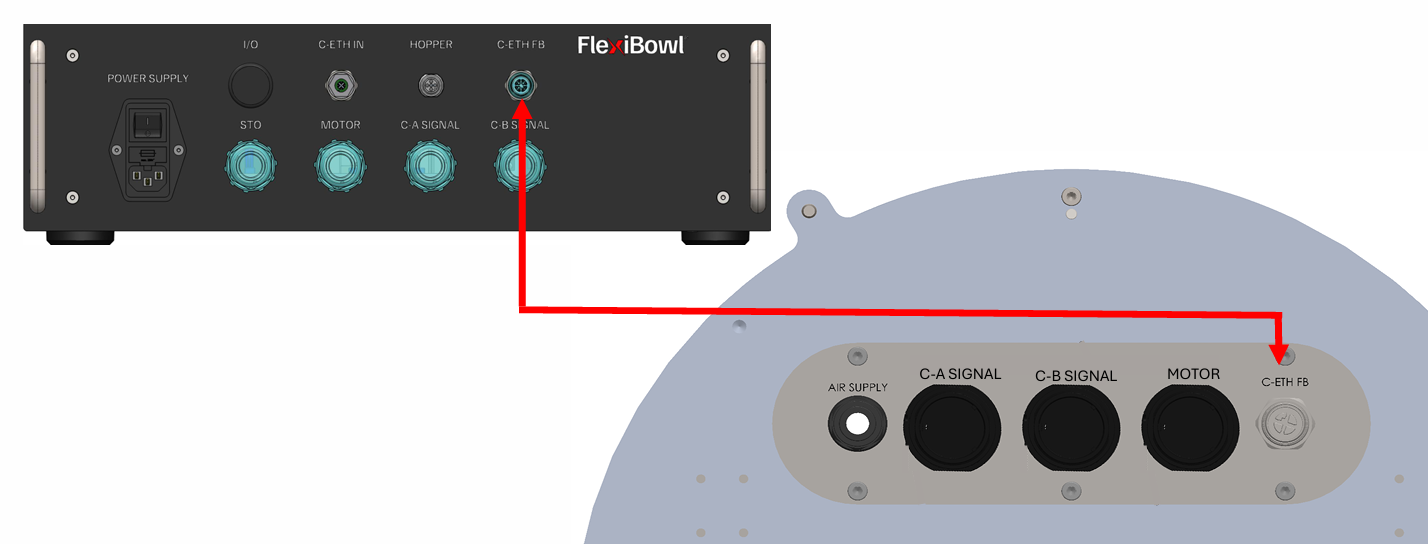
The rack communicates with the FlexiBowl® via 4 dedicated cables, each of which must be connected exclusively to the port with the corresponding label on the panel.
Attention
Connect each cable to the port with the matching label (e.g. MOTOR ↔ MOTOR, C-A SIGNAL ↔ C-A SIGNAL). A crossed connection can damage the system.
Action |
Image |
|
|---|---|---|
5 |
Connect the Ethernet cable (C-ETH FB) between the Rack and the FlexiBowl® — M12 D-code connector. |
|
6 |
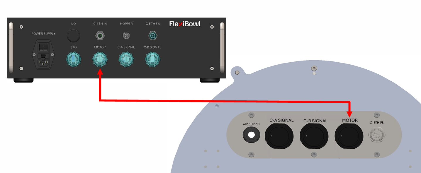
Connect the MOTOR cable.
9-pin connector: carries both the motor power and the STO signals to the FlexiBowl® (on the rack, STO and Motor are separate connectors; on the cable to the machine they are combined into a single 9-pin connector).
|
|
7 |
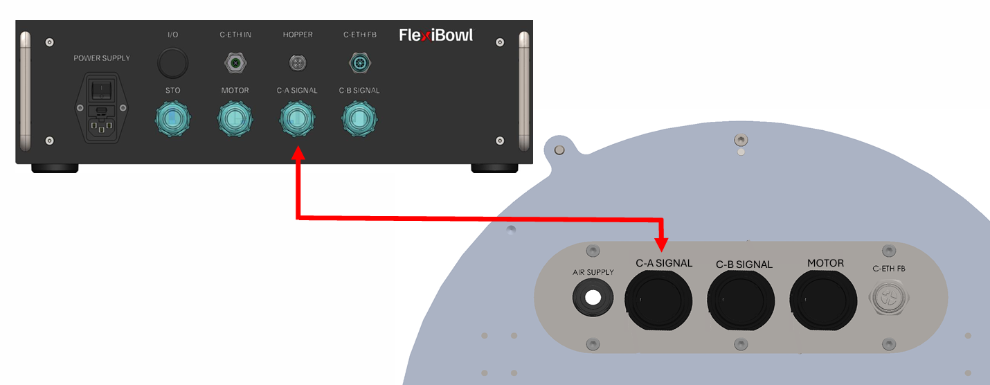
Connect the C-A SIGNAL cable — 19-pin connector for the analogue signals. |
|
8 |
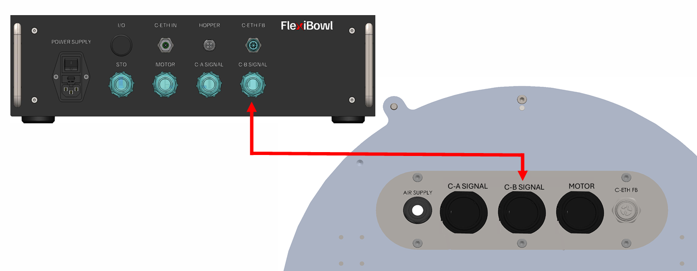
Connect the C-B SIGNAL cable — 19-pin connector for the digital signals. |
|
9 |
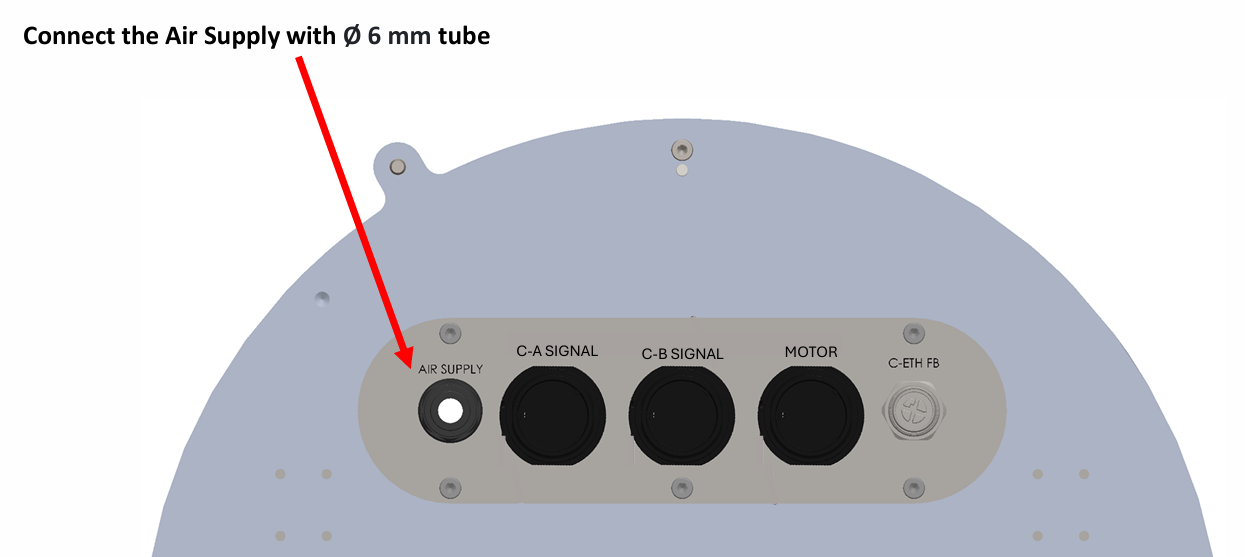
Connect the compressed air with an Ø 6 mm tube, directly on the machine panel. Note For the required air characteristics (pressure, ISO cleanliness class) refer to the Pneumatic Technical Data. |
|