

Bulk Feeder Configuration#
This page guides you through commissioning the vibrating Bulk Feeder, the optional accessory that feeds the FlexiBowl® continuously and uniformly. Follow the four phases in sequence: mechanical positioning and mounting, electrical connections, setting the communication address, and configuring the parameters from the software interface.
Position the Bulk Feeder with the correct orientation relative to the FlexiBowl® and secure it to the support bracket.
Connect the controller to the Bulk Feeder, to the FlexiBowl® (or to the rack) and to the power supply, following the connection order.
From the controller panel, set a unique address, required to communicate with the FlexiBowl® and any other Bulk Feeders.
Enable the Bulk Feeder from the FlexiBowl® web interface and set the amplitude, frequency and activation time of the vibration.
1. Positioning and mechanical installation#
Bulk Feeders are available in different sizes, each with its own maximum load:
Capacity |
Maximum load |
|---|---|
1.5 l |
1 kg |
3 l |
1.5 kg |
5 l |
6 kg |
10 l |
6 kg |
20 l |
6 kg |
40 l |
15 kg |
The Bulk Feeder arrives already assembled: it does not need to be assembled, only positioned and secured.
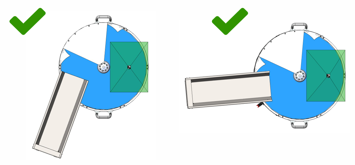
The Bulk Feeder chute must discharge the components directly into the working area of the plate, with an inclination that follows the profile of the FlexiBowl®.
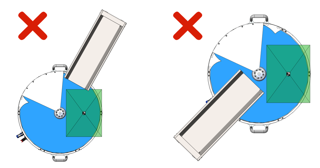
A chute that is too far from the work area results in inconsistent feeding and penalizes the performance of the application.
Steps:
Place the Bulk Feeder on a stable, horizontal surface, close to the FlexiBowl®, observing the correct orientation shown above.
If the Bulk Feeder is installed on the surface of a machine sensitive to vibrations, place an insulating, anti-vibration material between the two surfaces, to prevent the Bulk Feeder’s vibrations from being transmitted to the FlexiBowl®.
Secure the Bulk Feeder to the support bracket using the dedicated holes, with M8 screws: the standard Bulk Feeder has 4 holes in the base, while the smaller version (1.5 l) has 2.
2. Electrical connections#
Warning
Before making or changing any electrical connection, make sure the system is switched off. Always check that the earth conductor is correctly installed and intact: the electrical connection, including the earthing, must always be ensured for the machine to operate correctly.
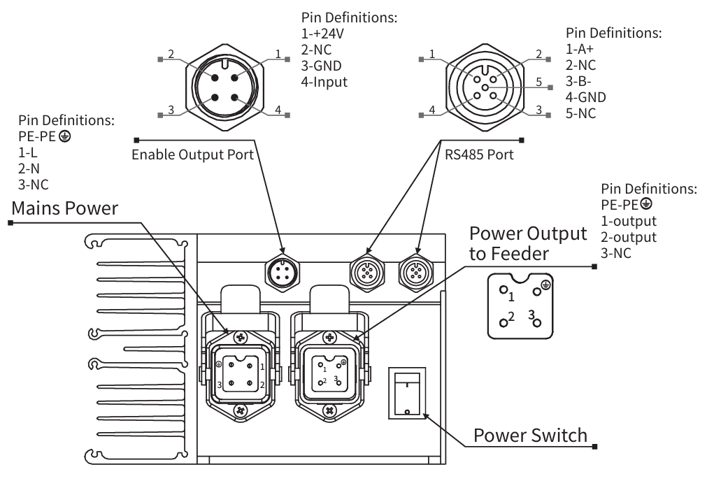
The Bulk Feeder controller has: a mains power input (earth, line, neutral), an RS485 connector for communication (A+, B-, GND), a power output to the Bulk Feeder motor and a main switch.
Steps:
Connect the controller to the Bulk Feeder using the dedicated cable.
Connect the controller to the FlexiBowl® using the M12 A-code connector (Modbus RTU communication). In multi-feeder installations with a rack, connect the controller to the rack instead.
Plug any unused connector with the appropriate cap, to protect it from dust and debris. The cap must provide a resistance of 120 Ω between the A+ and B- channels of the RS485 line.
Connect the power cable to the controller: always connect the controller end of the cable first, before connecting the other end.
With the controller switch in the OFF position, connect the power cable to the mains socket. The standard supply is 115 or 230 VAC ±5% (the 115 V version is available only on explicit request).
Switch the controller on using the main switch.
Tip
The Modbus RTU cable between the controller and the FlexiBowl® is available in lengths of 3, 5 and 10 m: see Modbus RTU cable.
Note
A single FlexiBowl® supports up to 4 Bulk Feeders. For multi-feeder installations, connect each Bulk Feeder to its own controller, connect the first controller to the FlexiBowl® (or to the rack) and chain the following controllers through the Bulk Feeder connector port (daisy-chain). Plug the unused port on the last controller in the chain and connect the power cable to each controller.
3. RS485 communication address#
Each Bulk Feeder controller must have a unique communication address on the RS485 network (parameter r, range 1–31). When there are several Bulk Feeders, make sure every controller on the same network has a different address.
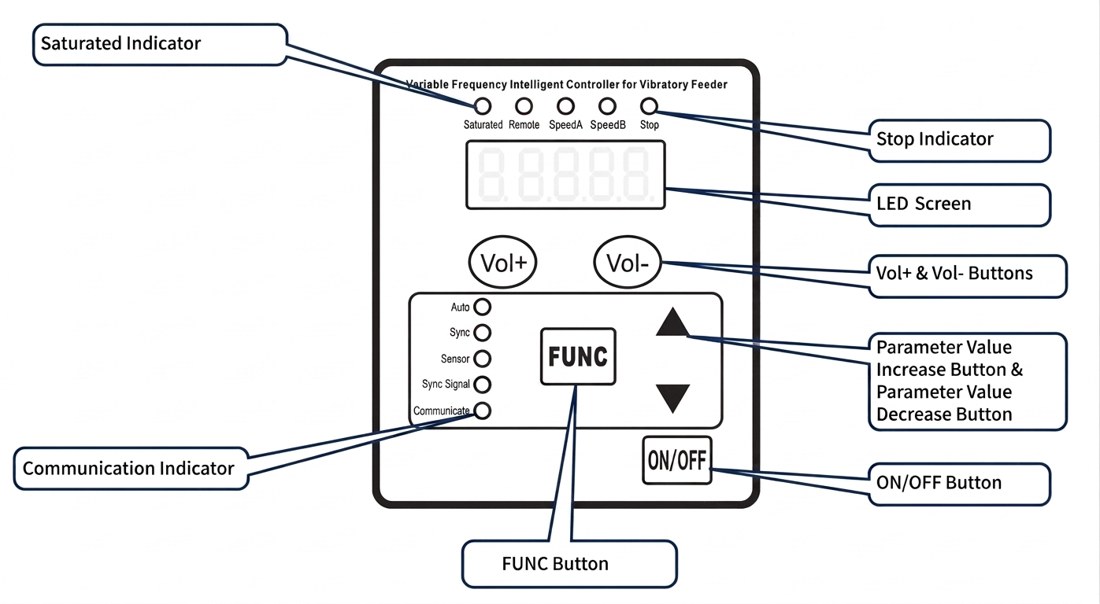
Steps from the controller panel:
Hold FUNC for 2 seconds to enter the basic parameter adjustment state.
Press FUNC repeatedly to select parameter r (communication address).
Press ▲ or ▼ to change the value (1–31).
Hold FUNC again for 2 seconds to exit and save.
4. Configuration from the software interface#
Once the connections are complete and the address is set, the Bulk Feeder can be configured and controlled from the dedicated page of the FlexiBowl® web interface.
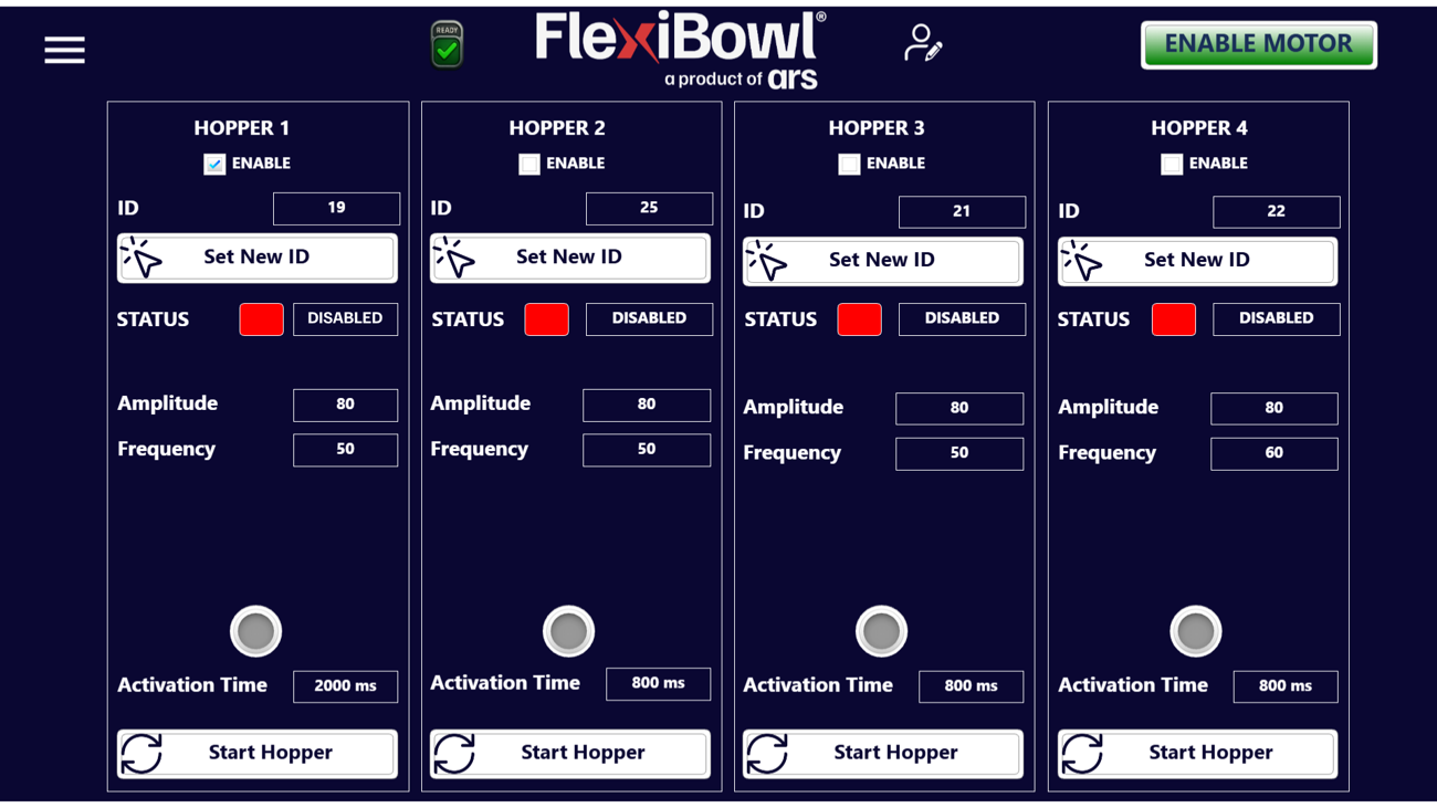
For each of the 4 available Bulk Feeders you can set:
Field |
Description |
|---|---|
Enable |
Enables the corresponding Bulk Feeder. |
ID |
RS485 address of the connected controller; use Set New ID to assign a new one via software. |
Status |
Current status of the Bulk Feeder (e.g. Disabled). |
Amplitude |
Amplitude of the vibration. |
Frequency |
Frequency of the vibration. |
Activation Time |
Duration, in milliseconds, of each vibration pulse. |
Steps:
Access the FlexiBowl® web interface and open the Bulk Feeder page.
Select Enable on the Bulk Feeder to be activated.
Check that the ID field matches the address set on the controller (step 3); if not, use Set New ID.
Set the initial values of Amplitude, Frequency and Activation Time according to the component to be fed.
Press Start Hopper to start the Bulk Feeder and check that it works; adjust the parameters until the component feed is continuous and uniform.
Note
The optimal values of amplitude, frequency and activation time depend on the component and on the geometry of the Bulk Feeder: adjust them gradually while observing the feed flow, starting from low values and increasing until a steady feed without jams is obtained.
Advanced controller parameters#
Common parameters#
The common parameters can be adjusted at any time with the Vol+ / Vol- keys, even while another parameter is displayed:
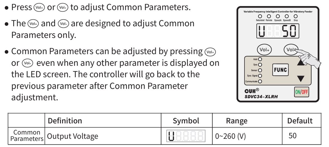
Definition |
Symbol |
Range |
Default |
|---|---|---|---|
Output voltage |
U |
0–260 V |
50 |
Basic parameters#
To access the basic parameters, hold FUNC for 2 seconds to enter, press FUNC to scroll through the parameters, ▲/▼ to change them, and hold FUNC for 2 seconds to exit:
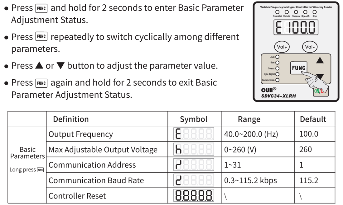
Definition |
Symbol |
Range |
Default |
|---|---|---|---|
Output frequency |
E |
40.0–200.0 Hz |
100.0 |
Maximum adjustable output voltage |
h |
0–260 V |
260 |
Communication address |
r |
1–31 |
1 |
Communication baud rate |
c |
0.3–115.2 kbps |
115.2 |
Controller reset |
— |
— |
— |
Controller reset#
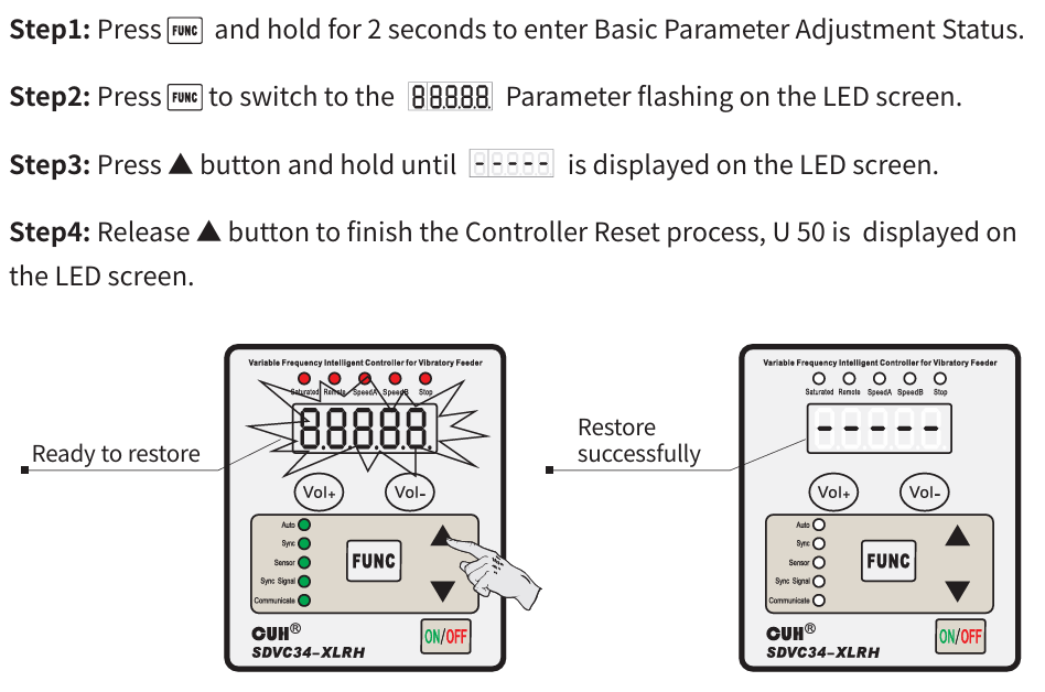
Hold FUNC for 2 seconds to enter the basic parameter adjustment state.
Press FUNC until the reset parameter (
88888) flashes on the display.Hold ▲ until
-----appears on the display.Release ▲ to complete the reset: the display will show
U 50, confirming that the operation was successful.