

Air Blow Kit#
Note
Implementing the blows requires a modification of the FlexiBowl® pneumatic system; for more information, refer to the pneumatic diagrams.
The blow kit (or Air Blow Kit) consists of the following parts:
Radial blow#
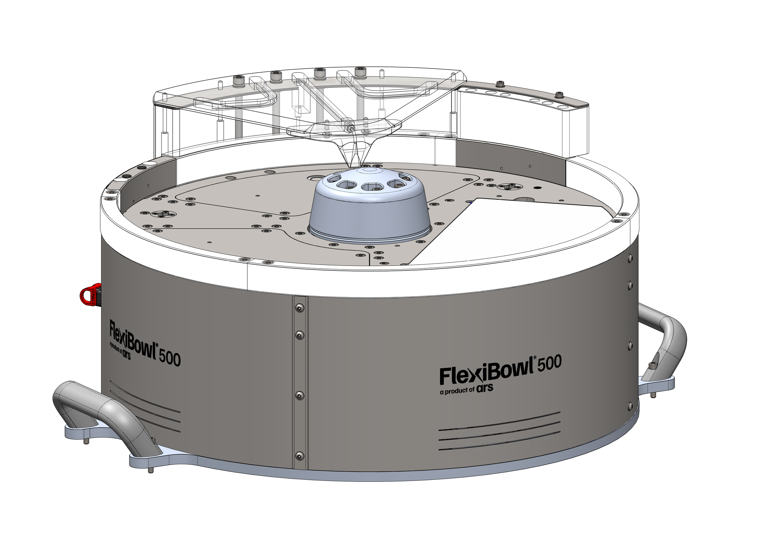
The radial blow consists of a cartridge that can be mounted in place of the standard diverter and has two radial holes at different heights: from one of the two, chosen by the operator according to the size of the parts to be handled, a jet of air comes out that moves the components away from the containment ring.
Mounting procedure#
Warning
Disconnect the electrical power supply before mounting the blows.
Step |
Operation |
|---|---|
1 |
Remove the diverter fixing screws |
2 |
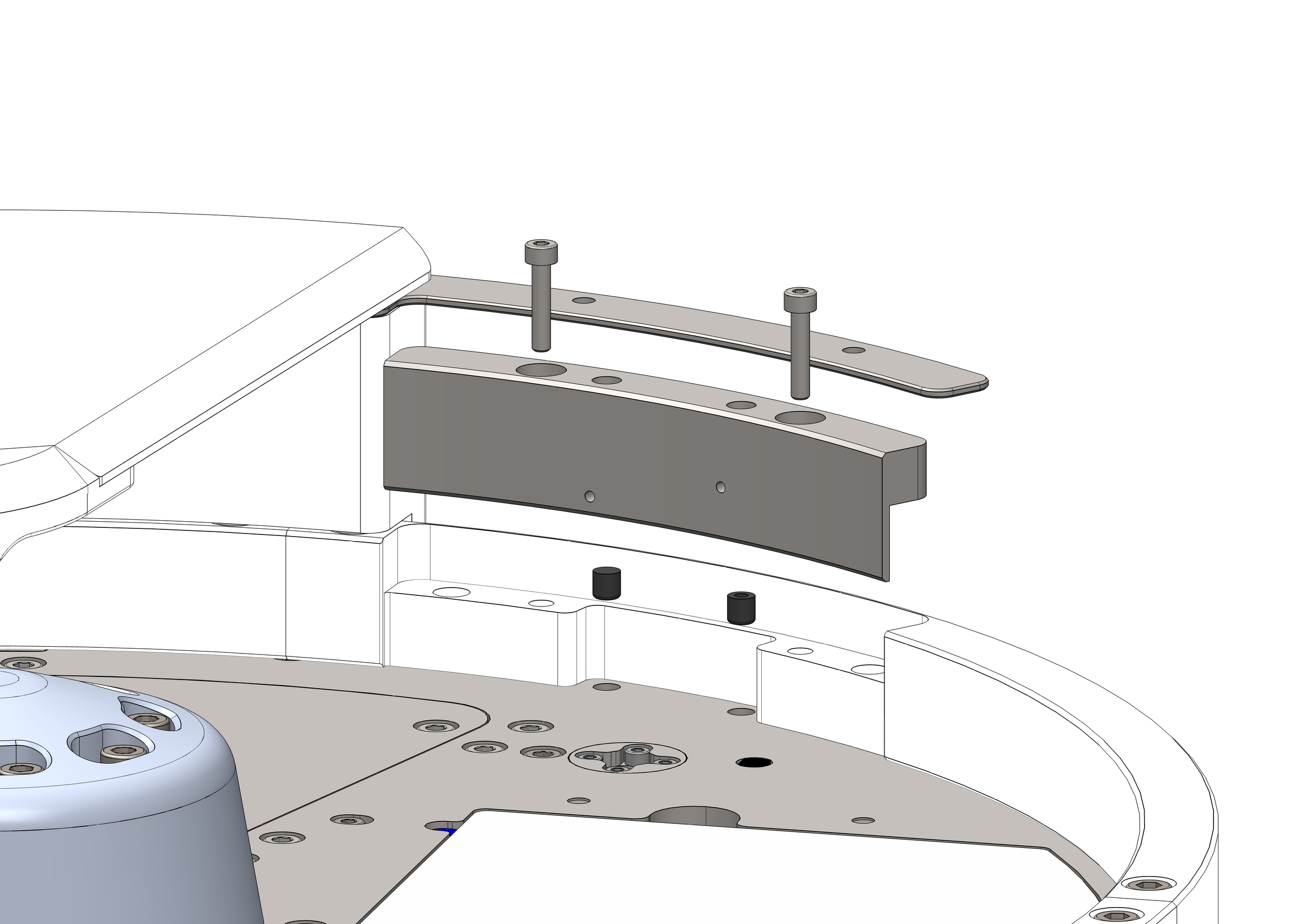
Unscrew the adjustment screws to remove the diverter |
3 |
Place the solid grommet and the drilled one in their seats according to the desired blow height |
4 |
Place the radial blow cartridge and secure it with the dedicated screws |
Adjustment procedure#
The radial blow can be adjusted both via software and mechanically, by turning the dedicated grub screw inside the cartridge with a 1.5mm hex key, taking care to lock its position by tightening the pusher with a flat screwdriver.
You can also choose the blow height by swapping the gasket with the plug under the cartridge:
Central blow#
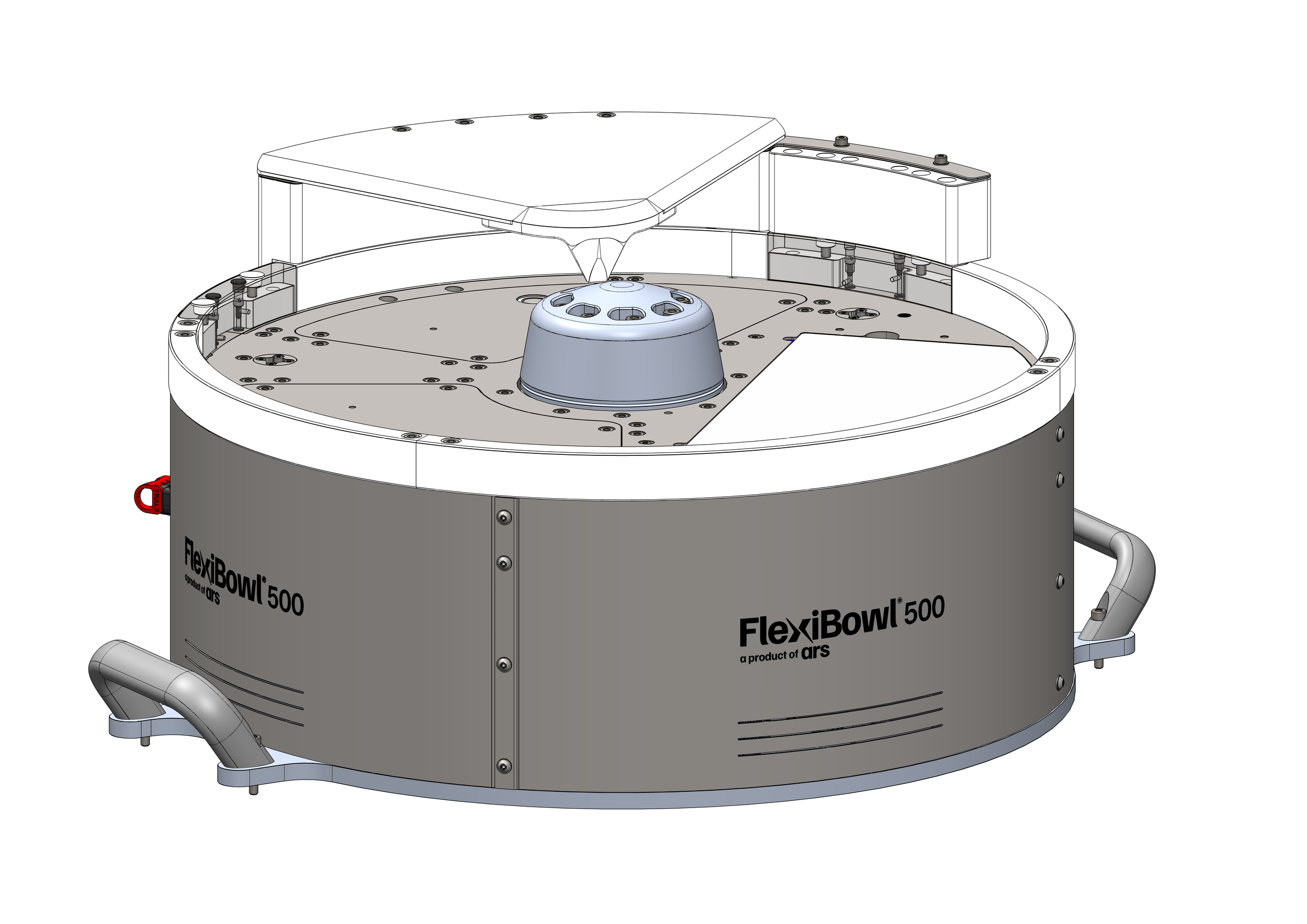
The central blow consists of a nozzle mounted on the tip of the flip screen, whose air jet is directed so as to move the components away from the disc clamping cap. Its purpose is twofold:
Bring the components over the flip to maximize its efficiency;
Prevent components from being considered unpickable because of excessive proximity to the disc clamping cap, which would cause the robot to collide.
Mounting procedure#
Step |
Operation |
|---|---|
1 |
Remove the entire flip screen-barrier assembly by unscrewing the four fixing screws |
2 |
Replace the screen with the central blow assembly |
3 |
Fix the new central blow-flip barrier assembly |
Adjustment procedure#
The blow intensity is adjusted via software. In addition, by tightening or loosening the adjustment grub screws of the radial blows by the same amount, it is possible to throttle or relax the air flow reaching the central blow.
Recommended applications#
They are to be preferred over the standard diverter when:
there is a need to handle components with small features or protrusions that could get caught in the gap between the diverter and the surface or rigid disc;
an anti-roll surface or rigid disc is used.
Checking correct operation#
Well-adjusted radial blows behave as follows:
The blow upstream of the flip brings the components to about half the radius of the FlexiBowl®, where the flip is most effective at turning over and separating the parts;
The central blow moves the parts away from the disc clamping cap so as to avoid collisions with the gripping tool;
The blow downstream of the flip moves the components slightly away from the edge of the FlexiBowl®, so as to prevent any collisions with the gripping tool.